WebAAer 2024 —— to toc

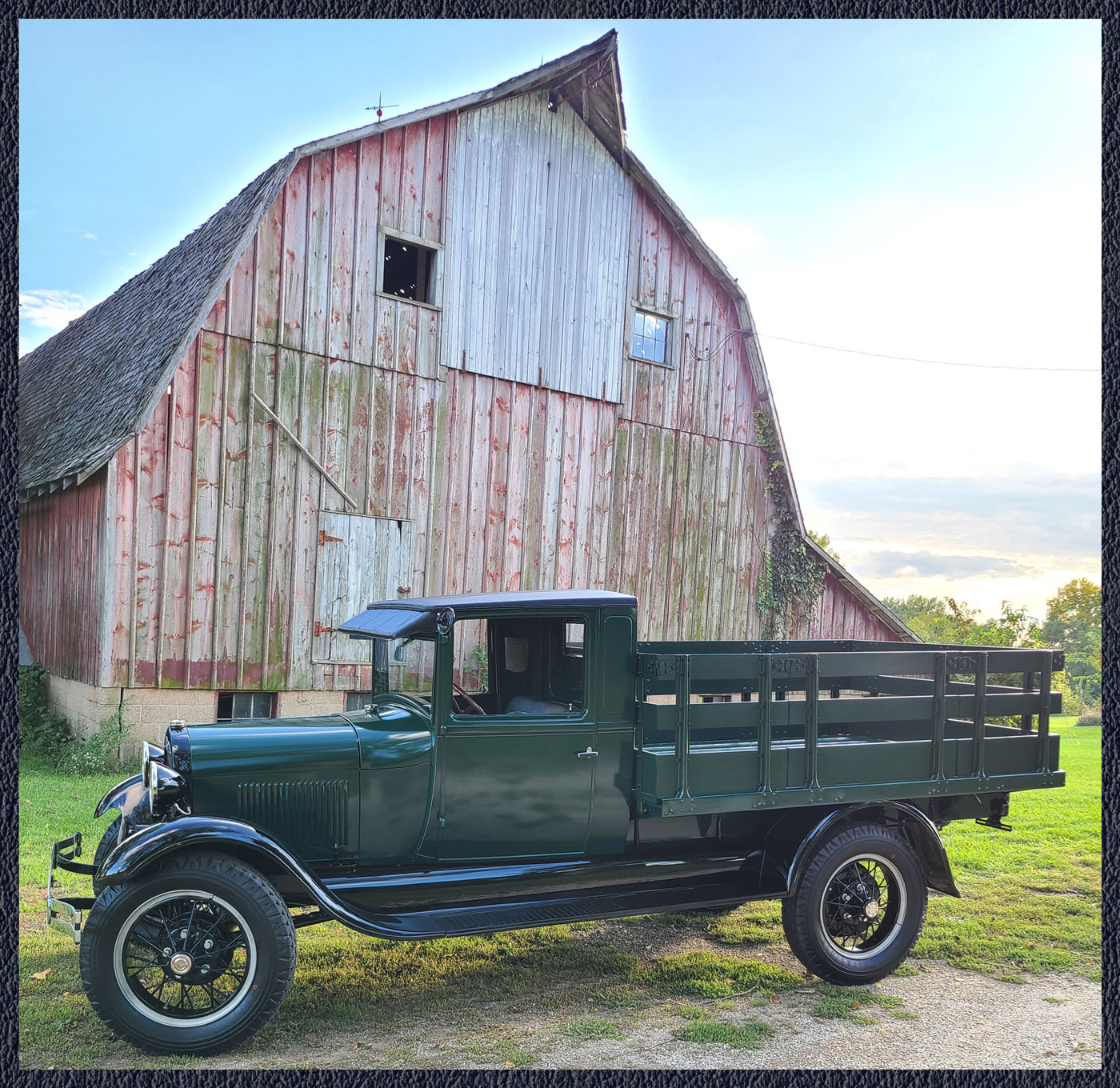
Table of Contents
In-document-links – click/tap – to return ◄
Double A’er Viewing Options
The three Double A’er viewing options are:
- web aaer – An Internet-based Double A’er – for viewing with an Internet-browser on the display of a monitor, tablet, or mobile phone. It is available to all club members. You are currently viewing a web aaer. Enjoy your visit.
- pdf aaer – A download .pdf-file Double A’er – created/formatted from the web aaer into thirty-two 8.5″ x 11″ pages. This is a downloadable file to be printed by members locally. Download access link is Double A’er Viewing (the access password is your membership ID). It is available to both pdf and print type club members. Although not recommended, it can be used for non-Internet viewing on the display of a monitor, tablet, or mobile phone.
- print aaer – A printed-USPS-delivered Double A’er – available to US members at extra cost. It is for print type memberships (US members only).
The web aaer and pdf aaer include links to additional AAFords.com site information. In addition, the Double A’er table of contents provides links to sections within the document. Larger articles contain table of contents with links.
Note – You are currently viewing a web-Double A’er (web aaer). For mobile phone viewing, landscape orientation is best for viewing images.
Note – There are three club membership aaer types – web, pdf, and print. See the FMAATC Status Report section of this Double A’er for more membership aaer type information.
FMAATC @ aafords.com
The home page for aafords.com is shown below. This site contains the information pages for the Ford Model AA Truck Club.
The FMAATC menu button (2nd button on the left) is a link to the club information pages.
All pages have the last updated date in the upper left below the menu buttons. There is a Search button (right end of the menu buttons) which allows searching the site. The home screen has the search field displayed below the menu buttons.
Home Page – Monitor Display
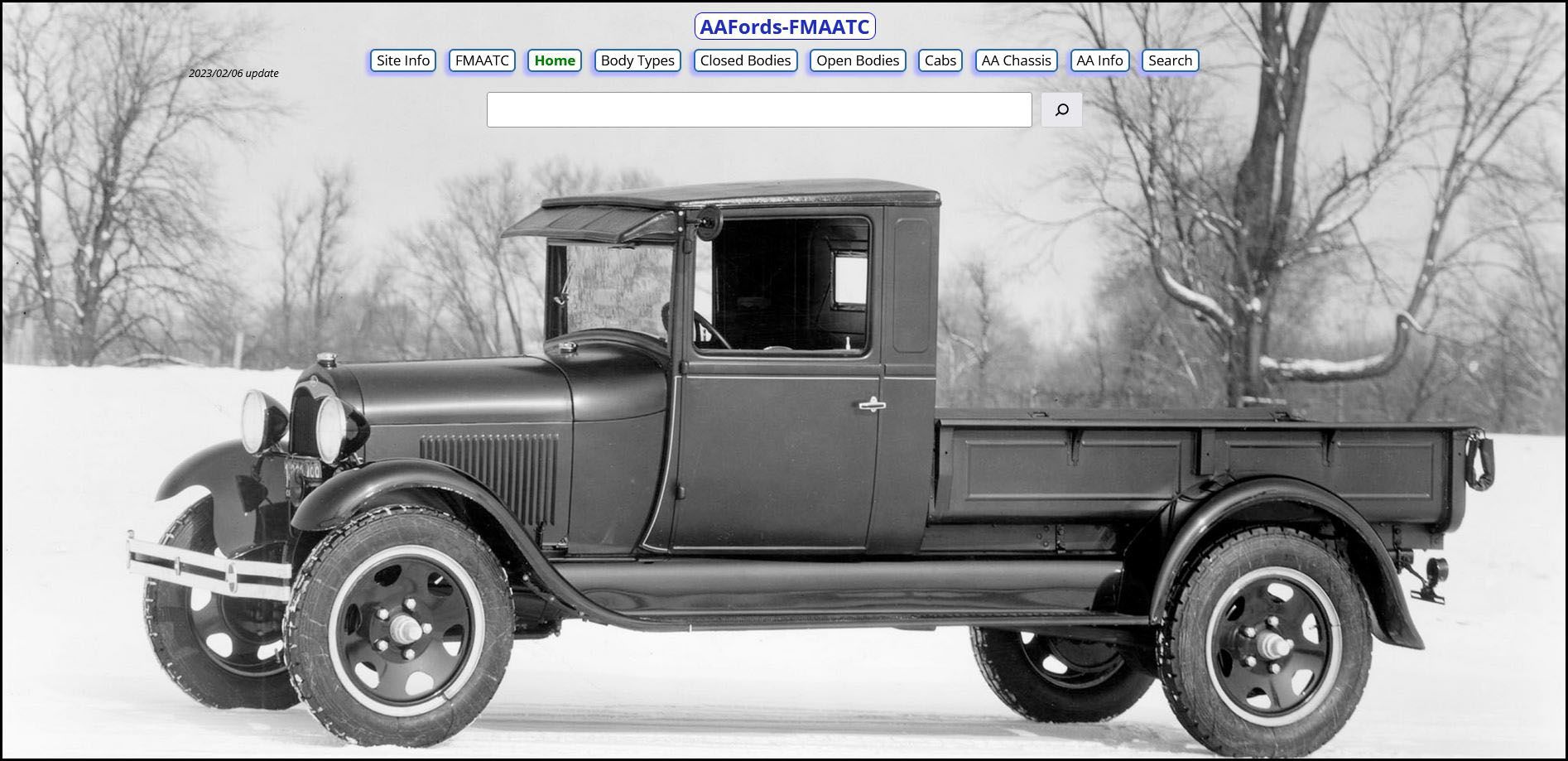
FMAATC Information Pages @ AAFords.com
Ford Model AA Truck Club
Membership
Newsletter
History
Store
Note that some of this information is contained within this issue of the Double A’er.
About FMAATC
Ford Model AA Truck Club Overview – The focus of the club is to provide a source of information so that collectors can identify, maintain, and restore their AA’s. The club was established in 1987 and became a MAFCA chapter (October 1987) and a MARC region (January 1989).
The Double A’er – This yearly newsletter is completed in April. It includes web, pdf, and print versions. The web version is the base newsletter (which started with the 2022 Double A’er).
The first issue was published in 1995. In this current issue – see FMAATC Store for past Double A’ers available; also see Double A’er Technical Articles listing.
Double A’er articles (provided as electronic documents) are welcomed and need to be received by the end of December.
The deadline for classified ads is February 15. Reproduction of Double A’er contents is prohibited without written permission.
President – Neil Wilson; fmaatc.org@gmail.com;
1365 Cherryvale Road; Boulder, CO 80303
Vice President – Bud Valerius; jbvaa31@outlook.com;
3605 Windsong Court; Manhattan, KS 66503
Membership – Renewal/new rates and information details are in the FMAATC Status Report section following.
Note that late renewal notice email and USPS letters are sent to non-renewed members in December—March.
Web aaer type members – An email is sent with instructions for web aaer access.
Pdf aaer type members – An email is sent with web aaer access instructions and download information of the pdf aaer.
Print aaer type members – The Double A’er package is sent. It includes a mailing sheet with renewal information and instructions for web aaer access and download information of the pdf aaer.
Ford Model AA Overview
Why “Ford Model AA”
The term “Ford Model AA” was coined because Ford assigned an “AA” model prefix to any chassis or body part number which was unique to the 1-1/2 ton Ford commercial vehicles (i.e. these were parts not used with the Ford passenger or commercial A-chassis).
Example: The 1st wheel = part 1015. Consequently, A-1015 = 1st Model A wheel and AA-1015 = 1st Model AA wheel.
Major AA Conversion Dates
1/29 – AA’s with Emergency Brakes – AA’s without emergency brakes were produced through 1928 (some into early 1929).
9/29 – AA’s with 4-Speed Transmission – The A-chassis 3-speed transmission was used through 8/29.
1/30 – AA’s with Optional Dual Wheels – With the conversion to a heavy-duty front end and spiral bevel rear end, the optional dual rear wheels were offered on the AA platform trucks.
6/30 – “B” Suffixed Body Types – new body types were:
76-B Open Cab; 82-B Closed Cab; 85-B Panel Delivery
Ford Model AA Lineup
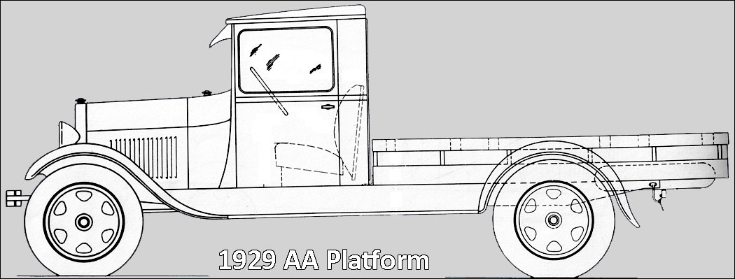
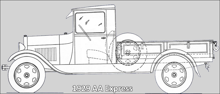
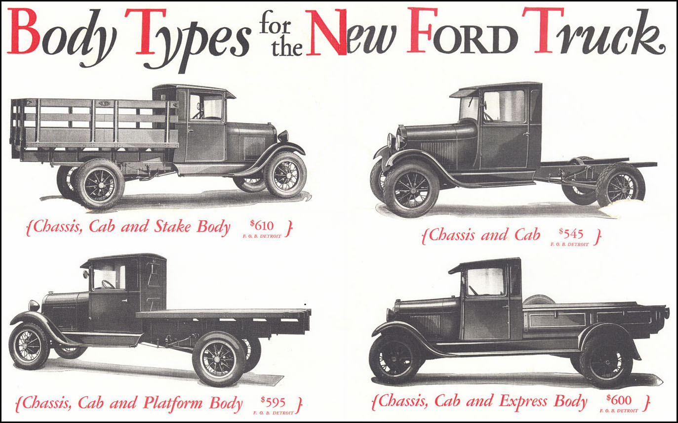
The most common AA cab and cargo body combination sold by Ford is shown in the drawings below. Shown are the two basic cab and platform AA trucks that rolled off the assembly lines. The open cab was also offered starting in May 1928 but had a much lower production volume.
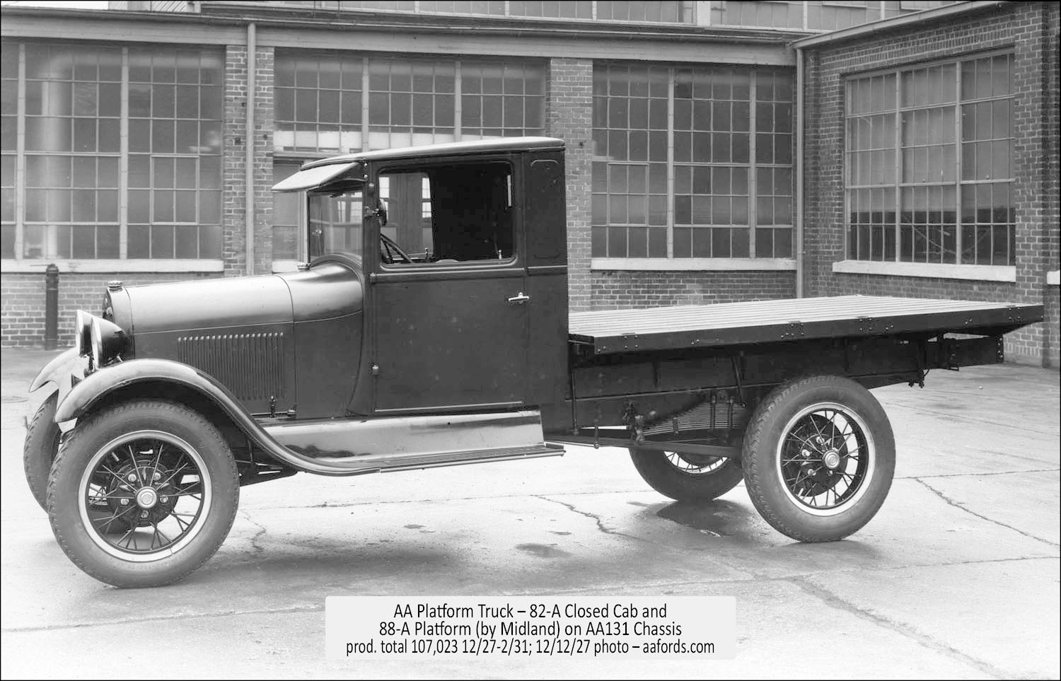
The 1929 AA Platform shown has the 12/27—6/30 Closed Cab (type 82-A) with 12/27—2/31 Platform (type 88-A). This AA is shown with rear fenders that were a factory production option through mid-1929 only.
Prior to 2/29, this AA would have had steel spoke wheels.
Starting 1/30, this AA would have had five spoke disk wheels like the 1930 AA Platform shown.
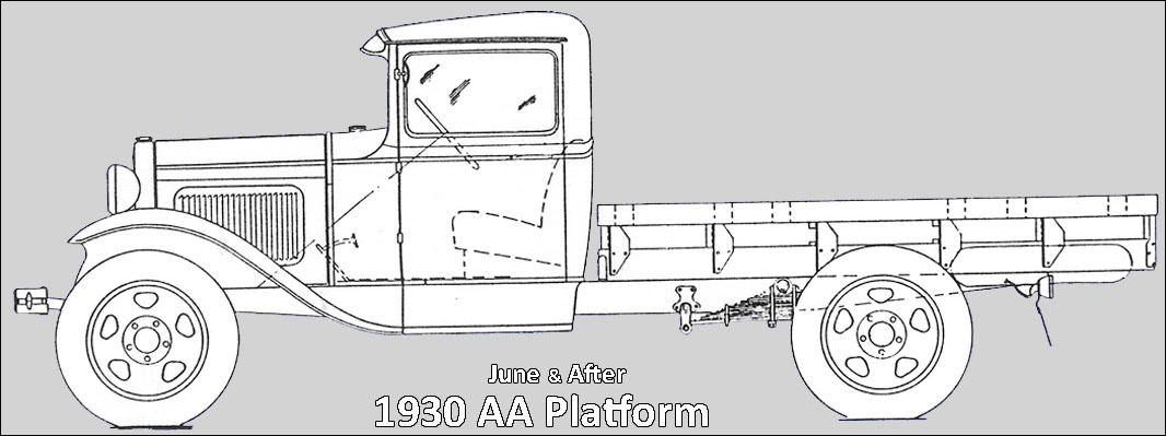
A 1930 AA Platform truck is shown. It has the 82-B Closed Cab that was used 6/30—6/32. The platform is the same type 88-A cargo body. It was the production platform through 2/31 for the 131-1/2” wheelbase AA’s.
Ford offered stake racks, grain sides, and stock racks as additional equipment for the platform. In addition, many AA platform trucks were fit with aftermarket sides by independent body suppliers (IBS) as well.
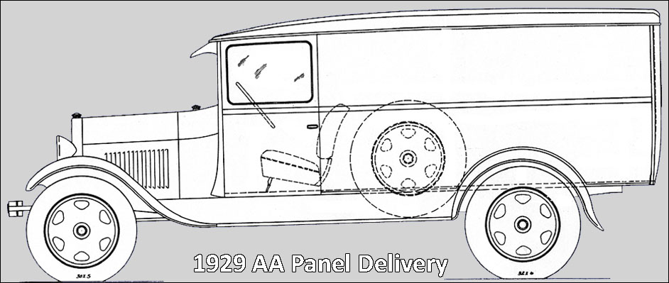
Ford offered an express and panel delivery truck as shown in the drawings below. The 1929 AA Express has the 89-A Express, open cargo body and 82-A Closed Cab (used through 6/30). The 89-A was replaced, starting 1/31, with the 195-A Express. The type 85-A Panel Delivery was in production from 8/28—6/30. A new panel delivery design (type 85-B) was introduced in 6/30. The only closed AA body types offered by Ford through 1930 were the panel delivery types 85-A and 85-B. The platform (with or without racks or sides), express, and panel delivery AA’s made up the bulk of the production line AA trucks.
Starting in late 1930, Ford offered AA trucks with dump, coal, and garbage bodies as complete units. In addition, starting in 1931, Ford expanded the AA production line to include a host of additional open and closed bodies. These were low production units such as the service car, ambulance, and bus. Some of these body types were carried forward for production into the 1932 BB truck line.
Ford sold the AA as a cab and chassis or as a chassis only. These units were fit with a wide variety of bodies and equipment supplied by various independent body suppliers (IBS).
??? FMAATC Status Report
Membership
Thanks very much to the ??xx members who donated to the club for the 20nn fiscal year.
As of March 31, 20nn, the “Ford Model AA Truck Club” has ??xx paid members. This includes ??xx new members who joined this year. For 20??—20??, ??xx members have not renewed.
Note – The per-member cost for 20?? is projected to be $??15.00 for print-members and $??6.00 for email-members. This includes costs for office work, Benson Ford Research Center photos-drawings, long-term costs (website domain and hosting, computer software-hardware), and Double A’er printing and mailing for print-menbers.
Renewal/Join information details are at
aafords.com/c/ms/
Renewal rates are as follows (two-year renewals are required):
..US & Foreign 20??—20?? – $10.00 web aaer member
..US & Foreign 20??—20?? – $20.00 pdf aaer member
..US ————– 20??—20?? – $28.00 print aaer member
Join (Start-up) membership rates are as follows (includes the current and upcoming Double A’er):
..US & Foreign 20??—20?? – $12.00 web aaer member
..US & Foreign 20??—20?? – $22.00 pdf aaer member
..US ————– 20??—20?? – $30.00 print aaer member
Treasury
Projected – Fiscal 20nn (4/25/??—4/24/nn) – The projected club treasury balance for fiscal 20nn is ??$xx,xxx after the 20nn Double A’er is completed. This figure includes the projected expenses for the production and completion or the Double A’er.
Actual – Fiscal 20?? (4/25/??—4/24/??) were:
$18,242.09 – ??Starting Balance
$ 6,273.48 – ??Income
$ 5,057.62 – ??Expenses
$19,457.95 – ??Ending Balance
FMAATC Store
Club Roster and Truck Registry
Available FREE. Two .pdf-files can be downloaded for viewing or printed. These files are updated at the end of April yearly.
Note – If you save these two .pdf-files in a separate folder on your computer you can use Adobe Acrobat Reader DC > Edit > Advance Search to find club members and AA body types owned by club member.
Club Logo Decals
Decals may be ordered at $.75 each plus $.75 US shipping or $1.25 USD foreign shipping. Checks must be in US $ with a US routing number.
Send payment and order information to:
FMAATC
1365 Cherryvale Rd.
Boulder, CO 80303
AA Photograph Albums
The two albums listed below are available for downloading – For both albums, the download price is $20.00.
You will be sent an email with a download link. You will have thirty days to finish the downloading.
Combine these Albums with Past Double A’ers for cost savings. See Past Double A’ers for details.
These two albums are also available on CD for $45.00.
Send payment and order information to:
FMAATC
1365 Cherryvale Rd.
Boulder, CO 80303
aafords.com@gmail.com
Truck Presentation Album (TPA)
National Ford Truck Sales Contest – Winter 1930—1931. There are 66 – 10×8 .jpg-image photographs as follows:
- 34 – AA (600 dpi)
- 14 – A (300 dpi)
- 07 – Group (300 dpi)
- 08 – Other (300 dpi)
- 03 – Text (300 dpi)
Truck Showroom Album (TSA)
May 1931 – There are 119 10×8 300 dpi .jpg-image photographs as follows:
- 04 – Cover/Lead-in
- 42 – AA Trucks
- 28 – AA Drawings
- 07 – A Vehicles
- 88 – A Drawing
- 28 – Specification
- 02 – A/AA Lub. Charts
Past Double A’ers
All of the past Double A’ers are available as a download-set or a CD-set. Technical articles about the AA Fords are found in these newsletters (see Double A’er Technical Articles).
A set consists of Double A’er .pdf-files which can be searched by the Adobe Reader’s Advanced Search feature found under the Edit menu.
The 1995 Double A’er is 8 pages. From 1996—2004 the Double A’er issues are between 20 and 30 pages. Starting in 2005, each issue of the Double A’er is 32 pages.
Note – For the download-set, you will be sent an email with a link to download folder “AAer-all” containing the newsletter .pdf-files. You will have thirty days to download folder “AAer-all” to your computer. This folder is large (about ??1 GB as of 20nn).
The download-set of Double A’ers require extraction from a .zip folder. If you don’t know how to accomplish the extraction, you can search the Internet for “how to extract files from a .zip folder for my operating system?”. You can also read “download-inst-AAer-all-folder.pdf” (shows extraction examples specifically for the “AAer-all.zip” folder for Windows 7).
An individual Double A’er issue can also be ordered (download only).
Double A’er Set – This is a set of .pdf-files for all Double A’er newsletters (1995—current issue) plus a .pdf-file of the 1987—1994 newsletters.
- Download-Set – $25.00
- Combined Download – $35.00 – An order for both the download Double A’ers and AA Photograph Albums.
- CD-Set – $50.00 – CD’s containing .pdf-files of each newsletter. The CD’s are mailed to your US address via USPS only.
For best speed of opening/navigating these .pdf-files, they should be copied to your computer hard drive. This also provides a backup of the CD’s.
- Double A’er Issue – $8.00 – Any individual .pdf-file Double A’er is available for downloading. You will be sent an email with a link to download the file you requested. You will have thirty days to download this file to your computer.
On-Line Order
Send payment to PayPal account fmaatc.org@gmail.com using your PayPal account (US funds only). Include a note indicating what your payment is for.
Send an email to fmaatc.org@gmail.com indicating that your PayPal payment was made. For a CD order, include your name and address (best to include your phone number).
Mail-In Order
Include a note indicating what your payment is for, email address (required), your name and address, and your phone number. Payment to be made to Ford Model AA Truck Club (FMAATC). All checks must be in US$ with a US routing number.
Send request with payment and your shipping address to:
FMAATC
1365 Cherryvale Rd.
Boulder, CO 80303
Double A’er Technical Articles
Through 2023
AA Truck Talk
AA Hub Caps – Part 2
By Neil Wilson, April 2024
AA Hub Caps – Part 2 Article Contents
Overview
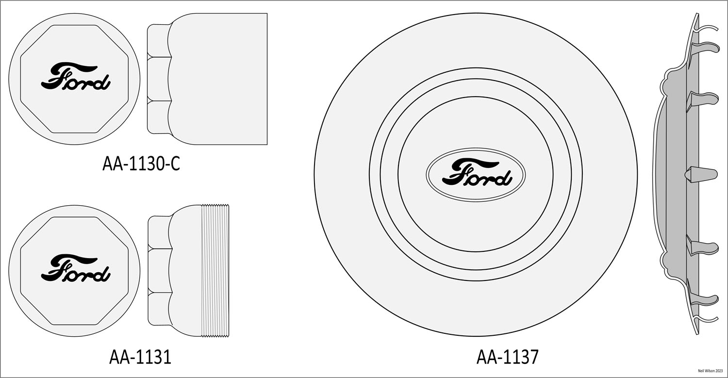
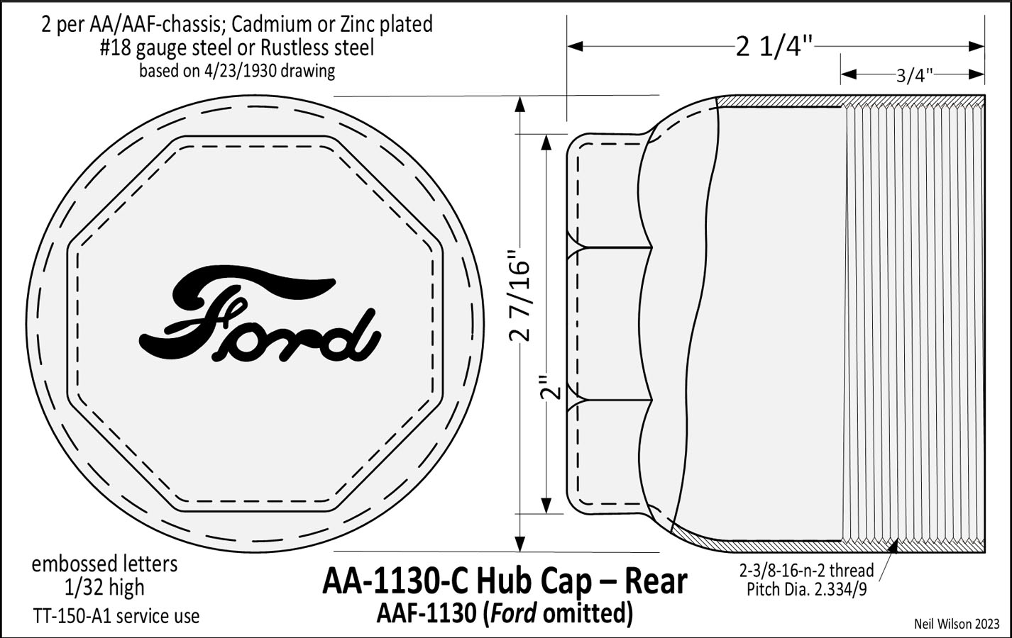
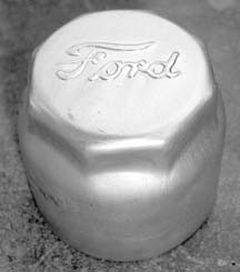
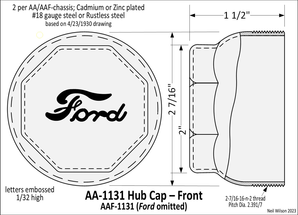
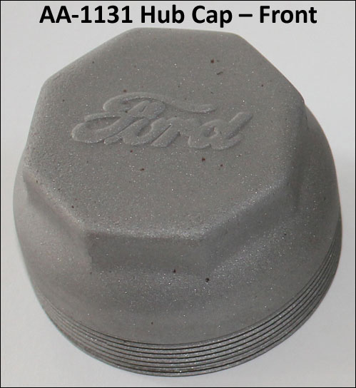
AA-1130-C Rear & AA-1131 Front Hub Caps
Ford engineering drawings dated 4/23/1930 were used as research for these AA-1130-C rear and AA-1131 front hub caps. The drawings and photos below provide visuals of these hub caps.
Starting January 1930, new front and rear ends along with a new heavier frame front cross member were placed into production. The new front/rear hubs were designed to accept screw-on type hub caps.
The AA-chassis rear hub caps were part AA-1130-C. This hub cap had a diameter of 2-7/16″ and was 2-1/4″ long. The AA-chassis front hub caps were part AA-1131. This hub cap had the same 2-7/16″ diameter with a length of 1-1/2″.
The AA-1130-C rear hub cap had 2-3/8-16-N-2 internal threads. The threads extended 11/16″—3/4″ from the inside end of the hub cap. It screwed onto the corresponding externally threaded rear hub.
The AA-1131 front hub cap had 2-7/16-16-N-2 external threads. The threads extended 7/16″—1/2″ from the inside end of the hub cap. It screwed into the corresponding internally threaded front hub.
The outside end of each hub cap was an octagon that was 2″ across the flats and 3/8″ tall.
The Ford lettering was embossed 1/32″ high. Two of each hub cap was required per AA-chassis.
These hub caps were made of #18 U.S. gauge steel or rustless steel. The finish was Cadmium or Zinc plating. This plating applied to both the steel and rustless steel hub caps. Note that this is based on the absence of any special finish requirements for the rustless steel hub caps on the Ford drawings.
These same hub caps (less the Ford name) were parts AAF-1130 and AAF-1131 for the Canadian AA-chassis. Two of each hub cap was required per AAF-chassis.
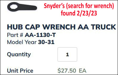
For the 2″ octagon wrench size end of these hub caps, an “AA Truck Hub Cap Wrench” was been found on 2/23/23. An oversized 12-point socket can be used for removal/installation of these hub caps. The original multi-wrench-sized Model T tool will not work since it has a 1-5/8″ octagon wrench.
On the Ford drawing, AA-1130-C rear hub cap was specified for servicing part TT-150-A1 (i.e. a factory part number). This was service part TT-1116 Rear Hub Cap.
Note: For the 1927 Ford Parts-Price-List (and prior dates) there are “Model” and “Factory Number” columns. And, the “Part Number” column contains the plain service part number + any part suffix. Consequently, part# 1116 was a rear hub cap with TT in the “Model” column and 150 in the “Factory Number” column.
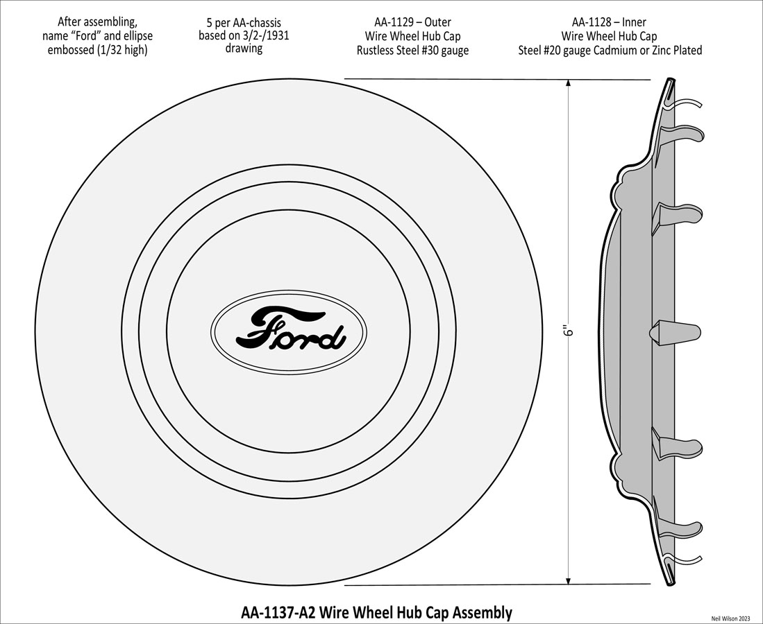
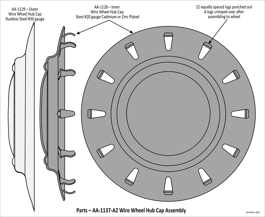
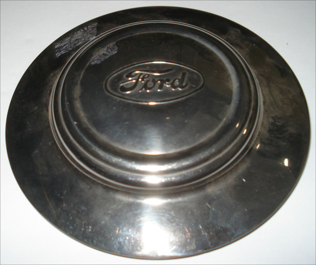
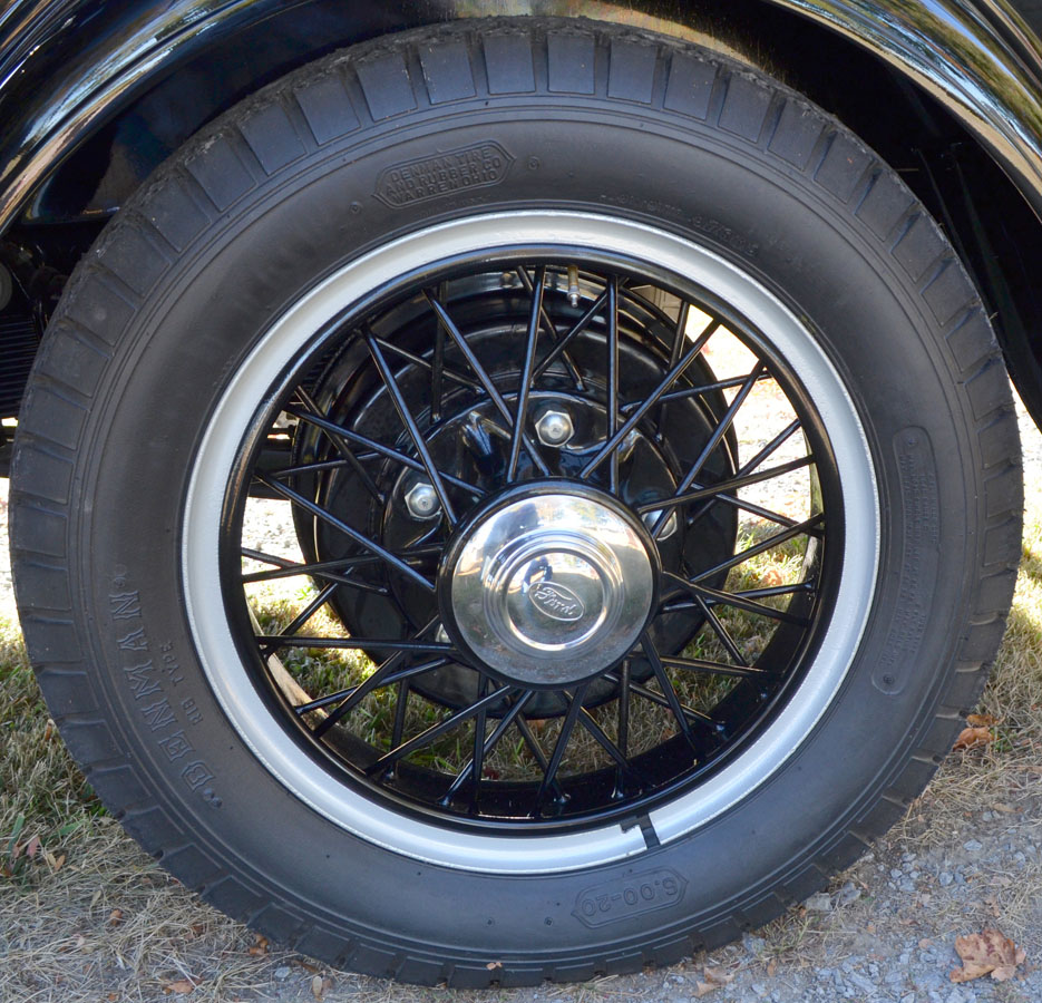
AA-1137 Wire Wheel Hub Cap Assembly
On the Ford Parts-Price-List, this hub cap is listed as – “AA-1137 hub cap — with AA-1015-E”. The diameter and height were specified as – “To be determined from shop practice”. It was approximately 6″ in diameter.
It was an assembly of AA-1128 inner and AA-1129 outer parts. The inner part was cadmium or zinc plated. The outer part was rustless steel with the outer surface polished a bright finish.
The 3/20/31 Ford engineering drawing specifies – “After assembling, emboss name “Ford” in script. Lettering and ellipse 1/32 high.” Consequently, the Ford script and ellipse can be seen on the inside of the assembly.
Note that AA-1015-E was a 20” steel spoke wheel used as optional equipment for body types 270-A, 275-A, 280-A, 285-A, 290-A, and 300-A.
The wheel had a larger bolt pattern and required special hubs and drums.
These wheels may have been made standard equipment for some of these body types at some time in 1931.
The inner part had 12 stamper lugs with a diameter of 5.510/5.520. The 3/20/31 Ford engineering drawing specifies – “4-lugs to be crimped over after assembling to wheel.”
To Above – Article “AA Hub Caps – Part 2” Contents
Brain Jensen’s 1928 AA Stake Truck

???featured image info – left column
???featured image info – right column
AA Body Type Tables
Section Contents
This section contains tables which provide Ford Motor Company Assembly Record Type (FMC ART) ledger based information about the forty-four US production body types and five cabs which Ford assembled as AA vehicle.
In addition, there is a table with AA-Chassis and Chassis-Parts information also based on FMC ART ledgers.
The above contents buttons are links to the tables as well as a link to table definitions.
| Closed Bodies (passenger and cargo areas – one body) | |||||
|---|---|---|---|---|---|
| Type | Body Name | Production Dates-Counts | Supplier | ||
| Start End | Count | Total*1 | |||
| Neil Wilson 2023 | |||||
| 85-A | Panel Delivery | 08/28 06/30 | 9,988 | Budd | |
| 85-B | Panel Delivery | 06/30 04/32 | 6,454 | Murray | |
| 210-A | Panel Delivery with rear-doors – AA157 | 12/30 04/32 | 1,233 | 1,502 | Murray |
| 210-A with tail-gate – AA157 | 04/31 03/32 | 269 | |||
| 270-A | Funeral Service | 04/31 10/31 | 17 | Briggs | |
| 275-A | Funeral Coach with side doors | 02/31 03/32 | 94 | Briggs | |
| 280-A | Ambulance with side doors | 02/31 03/32 | 90 | Briggs | |
| 285-A | Police Patrol (De Luxe ) | 02/31 03/32 | 45 | Briggs | |
| 290-A | Police Patrol (Standard) | 01/31 03/32 | 191 | Murray | |
| 300-A | Delivery (De Luxe) with rear-doors | 02/31 03/32 | 953 | 1,143 | Briggs |
| 300-A with tail-gate | 05/31 03/32 | 190 | |||
| 315-A | Standrive – AA112 | 07/31 12/32 | 445 | Bak Rau | |
| 330-A | Bus (School) – AA157 | 05/31 03/32 | 637 | Union City | |
| 330-B | Bus (Passenger) – AA157 | 11/31 02/32 | 48 | Union City | |
| AAAAA | aaaaaaaaaaaaaaaaaaaa aaaaaaaaaaaaaaaaaaaa aaaaaaaaaaaaaaaaaaaa aaaaaaaaaaaaaa | ||||
| *1 – 85-A/B each include 50% of June 1930 count: 85-A = 48, 85-B = 49 | see..FMC ART Adj. | ||||
| Open Cargo Bodies (Platform, Express, Special and Grain Body Types) | |||||
|---|---|---|---|---|---|
| Type | Body or Equipment Name | Production Dates-Counts | Supplier | ||
| Start End | Count | Total*1 | |||
| Neil Wilson 2023 | |||||
| Platform Body Types | |||||
| 88-A | Platform without equipment | 12/27 02/31 | 21,535 | 107,023 | Midland |
| 88-A with 134-A Stock Racks | 02/29 12/29 | 781 | unknown | ||
| 88-A with 134-B Grain Sides | 02/29 11/29 | 481 | unknown | ||
| 88-A with 188-A Stake Racks | 12/27 02/31 | 84,226 | Midland | ||
| 185-A | Platform without equipment – AA157 | 07/30 12/30 | 870 | 5,748 | unknown |
| 185-A with 186-A Stake Racks | 07/30 12/30 | 4,878 | unknown | ||
| 185-B | Platform without equipment – AA157 | 01/31 04/32 | 1,935 | 11,271 | Midland |
| 185-B with 186-B Stake Racks | 01/31 02/32 | 8,846 | Midland | ||
| 185-B with 238-A Stock Racks | 01/31 04/32 | 490 | Murray | ||
| 187-A | Platform without equipment | 03/31 06/32 | 1,025 | 7,585 | Midland |
| 187-A with 189-A Stake Racks | 03/31 06/32 | 6,413 | Midland | ||
| 187-A with 228-A Stock Racks | 03/31 03/32 | 147 | Murray | ||
| Express Body Types | |||||
| 89-A | Express | 12/27 12/30 | 11,353 | Budd | |
| 195-A | Express – light duty without equipment | 01/31 03/32 | 1,014 | 2,390 | Budd |
| 195-A with 196-A Canopy-Top | 01/31 02/32 | 1,321 | |||
| 195-A with 196-A Canopy-Top and Screens | 06/31 02/32 | 55 | |||
| 197-A | Express – light duty – AA157 | 01/31 04/32 | 348 | 858 | Budd |
| 197-A with 198-A Canopy-Top | 01/31 04/32 | 478 | |||
| 197-A with 198-A Canopy-Top and Screens | 06/31 02/32 | 32 | |||
| 239-A | Express – meat packers | 04/31 03/32 | 107 | Briggs | |
| 242-A | Express – heavy duty | 02/31 04/32 | 517 | Murray | |
| Special Body Types | |||||
| 199-A | Ice Wagon | 02/31 04/32 | 512 | Murray | |
| 229-A | Service without equipment | 01/31 03/32 | 328 | 580 | Briggs |
| 229-A with Crane & Cradle | 02/31 03/32 | 214 | Marquette | ||
| 229-A with Tow Bar Assembly AA-229402 | 02/31 03/32 | 38 | unknown | ||
| Grain Body Types | |||||
| 244-A | Grain without equipment – AA157 | 06/31 04/32 | 90 | 167 | Omaha |
| 244-A with Grain Extensions | none listed | 0 | |||
| 244-A with Stock Extensions white for visibility | none listed | 0 | |||
| 244-A with Grain and Stock Extensions | 06/31 04/32 | 77 | |||
| 248-A | Grain without equipment | 06/31 04/32 | 78 | 226 | Omaha |
| 248-A with Grain Extensions | none listed | 0 | |||
| 248-A with Stock Extensions white for visibility | none listed | 0 | |||
| 248-A with Grain and Stock Extensions | 06/31 04/32 | 148 | |||
| AAAAA | aaaaaaaaaaaaaaaaaaaa aaaaaaaaaaaaaaaaaaaa aaaaaaaaaaaaaaaaaaaa aaaaaaaaaaaaaa | ||||
| *1 – 1927 counts added: 88-A = 12, 88-A with 188-A = 120, 89-A = 17 | see..FMC ART Adj. | ||||
| Cabs (used with A and AA chassis – combined counts) | |||||
|---|---|---|---|---|---|
| Type | Cab (Body) Name | Production Dates-Count | Supplier | ||
| Start End | A/AA*1 | ||||
| Neil Wilson 2023 | |||||
| 75-A | Chassis Seat – with or without seat back – no FMC ART count | 09/31 ?? | no count | Ford | |
| 76-A | Open Cab – starting 1927 used on the A chassis | 05/28 06/30 | 65,141 | Ford | |
| 76-B | Open Cab | 06/30 04/32 | 6,560 | Ford | |
| 82-A | Closed Cab – starting June 1928 used on the A chassis | 12/27 06/30 | 292,105 | Budd | |
| <82-B | Closed Cab – soft top | 06/30 09/31 | 170,391 | Ford Budd | |
| Closed Cab – steel top | 08/31 07/32 | Budd | |||
| AAAAA | aaaaaaaaaaaaaaaaaaaa aaaaaaaaaaaaaaaaaaaa aaaaaaaaaaaaaaaaaaaa aaaaaaaaaaaaaa | ||||
| *1 – 1927 A/AA counts added: 76-A = 78, 82-A = 153 | see..FMC ART Adj. | ||||
| 76-A/B and 82-A/B each include 50% of June 1930 count | |||||
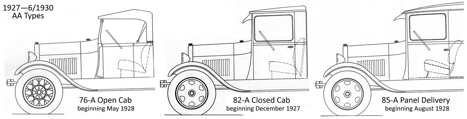
Table Definitions
The tables above lists Ford, US production assemblies based on FMC ART. The five are: Closed Bodies, Open Cargo Bodies part 1 and 2, Cabs, Hoists/Non-Production Bodies, and Chassis and Parts.
The Open Cargo Bodies table has sub-categories of Platform, Express, Special, Grain, Dump, Coal and Garbage.
Note – The Indianapolis Service Letter of 5/16/30 announced the assignment of “Body Model Numbers” (referenced as “Types” soon afterwards). Body Model Numbers (Types) were assigned to both current and past A and AA bodies. The types corresponded with a body part number grouping (example – platform type 88-A was for body parts number group 88000-88999).
Table Columns Definitions
Type – Ford assigned body type. Type is not repeated for Types with multiple rows.
Body Name – Ford assigned name. The name is followed with “AA157” or “AA112” for body types assembled on those chassis. All other bodies were assembled on the AA131 chassis. Multi-row Types have the Type repeated at the beginning of the name.
Start End (Dates) – Body production date range based on FMC ART monthly ledgers or Ford announcement dates when needed. For example – the ledgers do not show 88-A end date or 187-A start date. Therefore these dates are based on the March 10, 1931 Indianapolis Service Letter announcement of the conversion to the 187-A.
Count – Blank for Types with a single row. Otherwise, this shows the row Count for multiple-row types.
Total or A/AA – Total ledger count for a Type based on Start End dates. Also, see FMC ART Adjustments below.
Supplier – Body manufacturing company gathered from various sources (supplier’s body ID’s are not listed).
FMC ART Adjustments
Ford Motor Company – Assembly Record Types
1927 Adjustments
For 1927, counts of 268 for the AA chassis and 99 for the A chassis were the only ledger information provided. Based on 1929-1930 ledger information, estimated %’s were determined. These %’s were used to calculate counts which have been added to totals as follows:
- 76-A Open Cabs – 78 (33.8% of 367 – A+AA chassis)
- 82-A Closed Cabs – 153 (66.2% of 367 – A+AA chassis)
- 89-A Express body – 17 (6.3% of 268 – AA chassis) – may actually be zero (no Ford info. or photos to confirmed 89-A start date)
- 88-A Platform – 12 (4.5% of 268 – AA chassis)
- 88-A with 188-A Stake Racks – 120 (44.8% of 268 – AA chassis)
June 1930 Adjustments
This month was the conversion time for the Open/Closed cabs and the Panel Deliveries. Table counts for these six types include 50% of the June 1930 ledger counts (actual counts are unknown and may be different):
- 76-A/B – 50% of 1,089 (554/545)
- 82-A/B – 50% of 14,620 (7,310/7,310)
- 85-A/B – 50% of 97 (48/49)
To Above – AA Body Type Tables Section Contents
FMAATC Meeting
20nn city, st??
about future 20nn meeting?????????
Reproducing Floor Boards
Ford A & AA
By Brian Jensen – Late 2023
Covers #1 (slant) and #2 (flat) floor board designs.
Article Contents
Figures List
- Fig 1 – Linderman dovetailing machine
- Fig 2 – Board dimensions and orientation
- Fig 3 – Dovetail dimensions
- Fig 4 – Dovetail router bit
- Fig 5 – Making the groove
- Fig 6 – Making the dovetail
- Fig 7 – Clamping the boards
- Fig 8 – Cutting the edge bevels
- Fig 9 – Drilling the dowel holes
- Fig 10 – Dowels installed
- Fig 11 – Fitting up in the cab
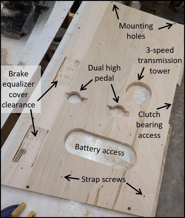
- Fig 12 – Floor board #2 features (underneath view)
Figures List Cont.
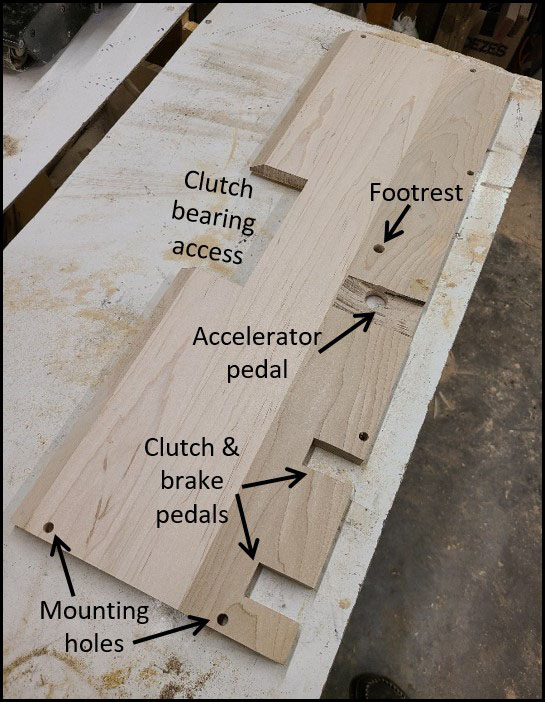
- Fig 13 – Floor board #1 features (underneath view)
- Fig 14 – Steps to create features
- Fig 15 – Brake and clutch slots
- Fig 16 – Accelerator pedal hole and clearance
- Fig 17 – Clearance for brake equalizer cover
- Fig 18 – Dual high holes and clearance
- Fig 19 – Marking holes for welting
- Fig 20 – Welting mark
- Fig 21 – Punching welting hole
- Fig 22 – Underneath of finished floor board #2
- Fig 23 – Finished floor boards installed in cab
Introduction
This article is written to assist those wishing to reproduce their own floor boards for the Model A Ford. From the beginning of production and into 1929, Model A floor boards were made by assembling several hardwood boards together side-by-side to make a solid wooden floor, or “floor boards” for the vehicle. These floor boards utilized dovetailed and glued edge joints between the boards for strength.
The hardwood floor boards illustrated in this article were made for an early 1928 AA 82-A closed cab truck. Many of the techniques used to create these floor boards may be utilized to make the floor board features for other Model A’s and AA’s.
Generally, the Model A pickup with closed or open cab and the A panel delivery used the same floor boards as the Model AA commercial trucks with cab or AA panel delivery.
During 1929, hardwood floor boards were gradually replaced with plywood versions that were used for the remainder of production. Those wishing to create plywood floor boards will skip the dovetailing and assembly steps but can utilize the steps for sizing, creating features, finishing and welting.
Before beginning, you should determine the specific requirements for your floor boards in terms of materials, dimensions and features for your vehicle.
Whether reproducing floor boards for cars or trucks, the following areas should be referenced within the Model “A” Ford Judging Standards & Restoration Guidelines(1) to determine the specific changes through production and how they apply to your vehicle:
Area 11 – Carpets and Mats
Supplement A – Early 1928 Vehicles
Supplement E – Heavy Commercial Vehicles.
For Model AA commercial trucks there is a great deal of information available in the Floor Boards page on the AAfords.com site(2).
This same information is within two AA Truck Talk technical articles written by Neil Wilson and published in The Double A’er newsletter(3). Much of this information can also be used for the pickup, A panel delivery and cars.
Preparing The Boards
For all floor boards, you need to start with a “blank” piece of material large enough to cut the floor board from.
If using plywood, the floor board profile is simply cut from a sheet of plywood larger than the floor board. The plywood specifications on the original Ford drawing were to be 11/16 inch thick “5-ply fir”.
If using solid hardwood, the blank must first be created by joining several boards together until the resulting blank is larger than the floor board.
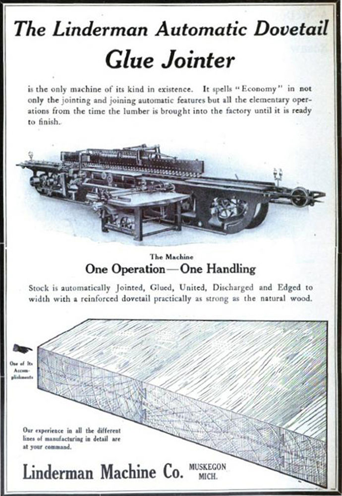
Ford’s production process utilized a Linderman machine to mass-produce the floor board “blanks” by dovetailing, gluing and assembling the hardwood boards all in one machine. Figure 1 shows a vintage advertisement for the Linderman machine(4).
The hardwood specified by the original Ford drawing was “maple, beech, birch, elm or oak” and the boards were to be “free from full knots, checks and warp”.
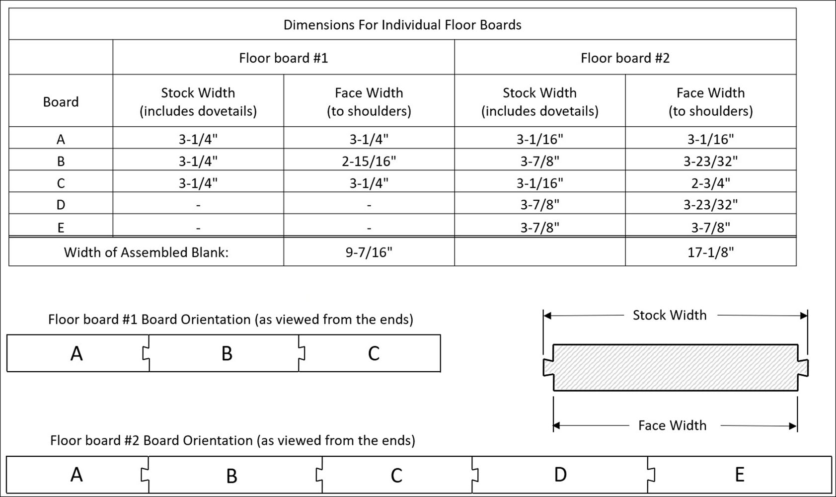
The hardwood that I used was soft maple, which is strong and has a closed grain with a smooth, even texture. Floor board #1 (angled floor board inside the cowl) was made from 3 boards and floor board #2 (horizontal floor board in front of seat) from 5 boards. Ford drawings do not specify the number or width of the individual boards, other than to “Make up from Linderman stock”. The drawing also states the stock boards are to be “in widths of 3 inches and over” before cutting the dovetails. Board widths would have been random when using the Linderman machine.
Figure 2 shows the two floor board cross sections, with the suggested number of boards and widths. The widths were chosen to resemble original floor boards but can be adjusted to best fit your needs. Also shown are the dovetail orientations with the center board having a dovetail on two edges. While not required, this orientation has been observed on original floor boards and most likely depended on operation of the Linderman machine.
Once glued up, the overall size of the rough blank is the sum of the board face widths and should be slightly larger than the final floor board to allow for cutting of the perimeter shape.
The example board widths were chosen to provide 1/4 inch of excess material after assembly. Note that the length of the boards must also be greater than the final width of the floor board.
In order to ensure that your finished floor boards are good fitting and flat, all individual boards should be planed to the final thickness of 11/16 inches and jointed for straight, square edges prior to dovetailing. This is very important as otherwise you may find dovetails that are too large or small, or grooves that are off center.
Your planed and jointed boards should now be ready for the dovetails.
Cutting The Dovetails
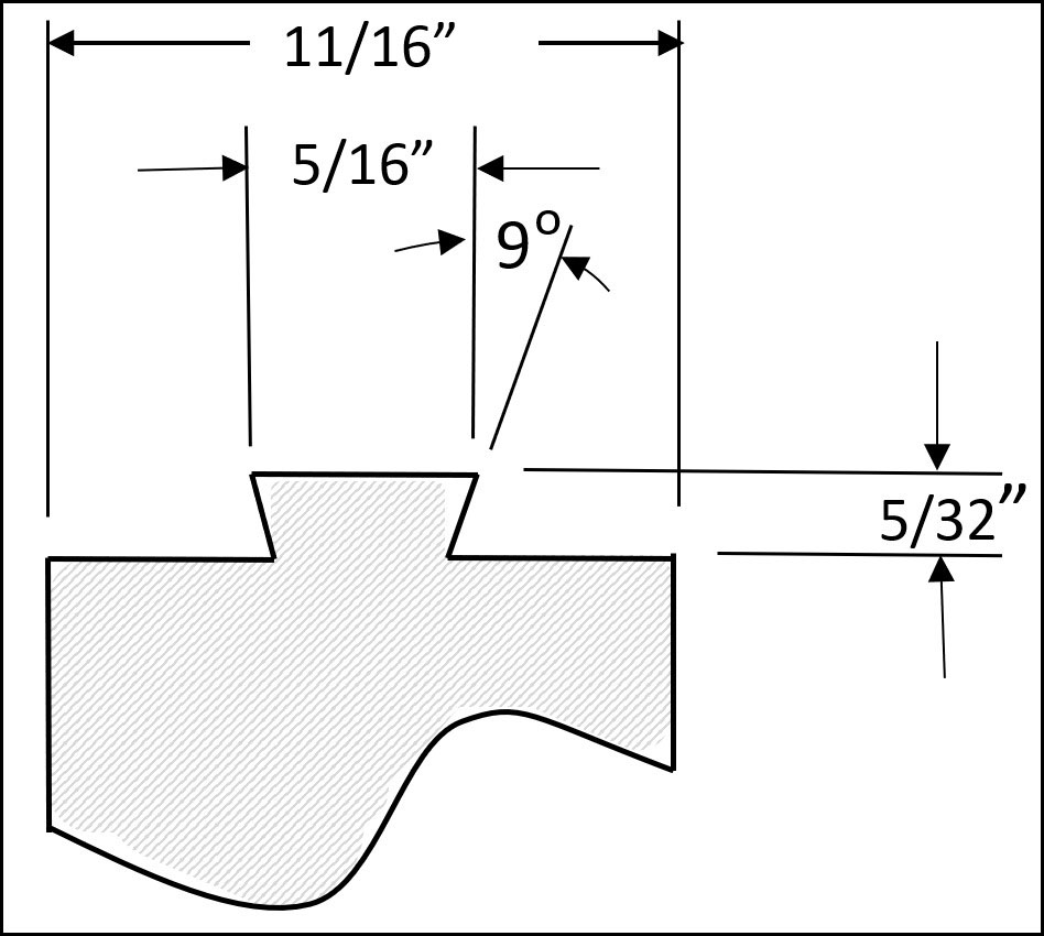
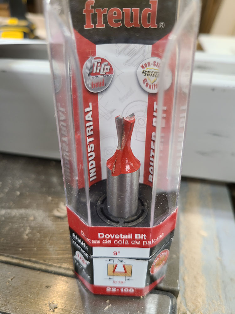
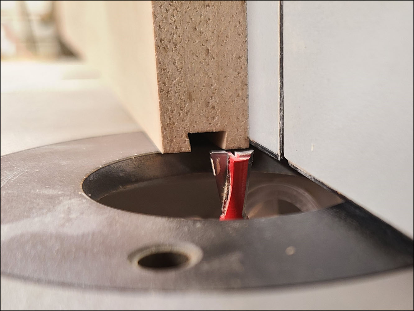
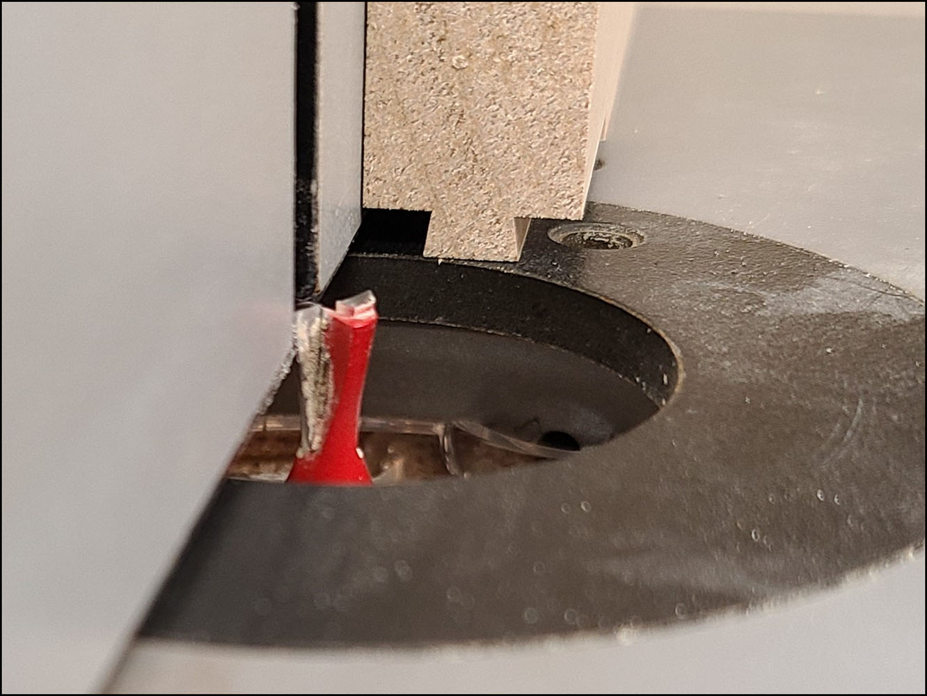
The dovetail dimensions shown in Figure 3 are based off measurements from original floor boards. I used a 5/16 inch, 9 degree dovetail bit with 1/2 inch shank as shown in Figure 4. The router was mounted underneath a router table with fence. Figure 5 and Figure 6 show the dovetail set-ups for the tails and grooves.
The groove is made in a single pass and needs to be accurately centered in the edge of the board. The dovetail requires two passes, one on each side of the board/tail.
Use a calipers to help adjust the set-up until the grooves and dovetails are centered and slide together easily. Run some tests with sample boards before making the final cuts.
If the dovetails are too loose, you risk losing strength. If the dovetails fit too tight, they can be difficult to assemble and there is an increased chance of breaking off the tail during assembly.
Assembly
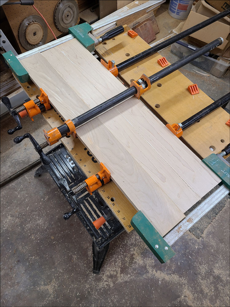
To assemble the floor boards, brush a quality waterproof glue on the dovetailed edges. Slide the boards together and clamp as shown in Figure 7, making sure they are clamped evenly to hold the boards flat. Alternate the clamps on each side of the boards and don’t over tighten. Let them dry until the glue is set.
At this point, there may need to be some leveling of the boards/joints, however don’t overdo. Original floor boards were mass produced and covered by a mat or carpet, so not much effort was made to create a fine surface.
At this point, the floor board profile can be laid out on the blank. Dimensions can be referenced on drawings or even measured from original floor boards.
Measurements should be validated relative to your actual cab as much as possible, including the location of the transmission tower and other controls.
Perimeter Fit Up
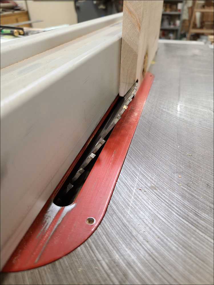
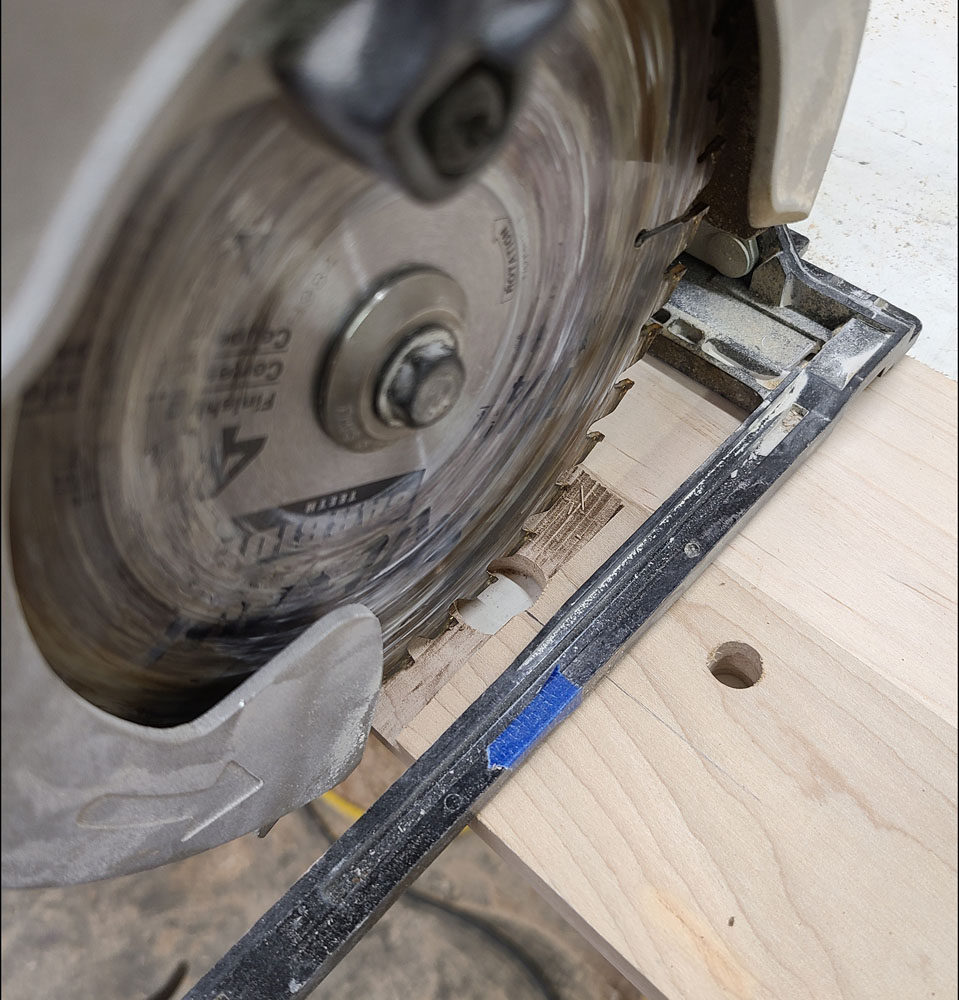
Now the floor board perimeter can be cut, including the beveled edges between the two floor boards. Figure 8 shows a representation of the beveled edge being cut on the table saw, with guards removed for visibility.
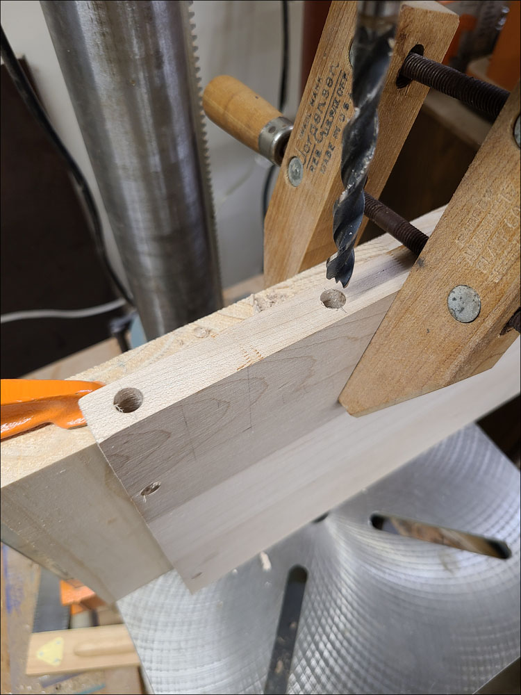
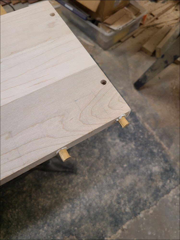
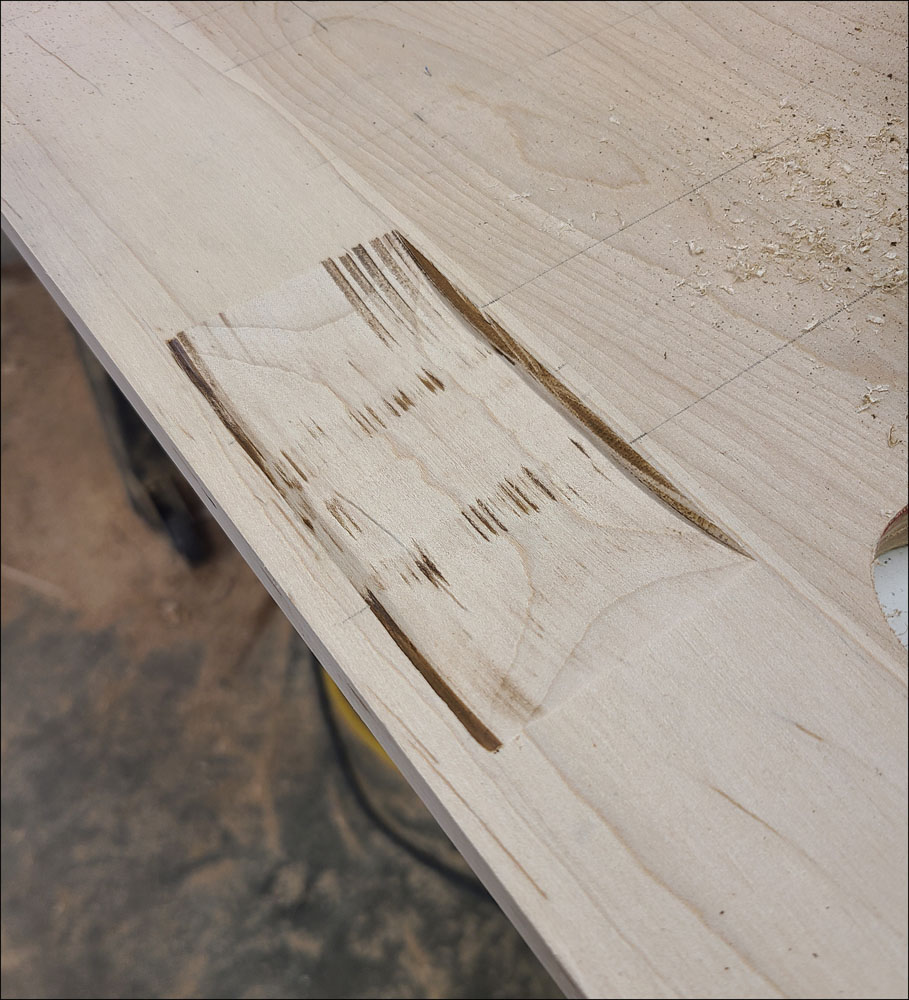
Before cutting the slots for the brake and clutch pedals, strengthen this area with reinforcement dowels inserted from the edge. Drill the holes for the dowels using a brad point drill bit as shown in Figure 9. The use of a drill press will help ensure the hole is straight into the center of the board. Make the dowels with a little extra length and groove them lengthwise to allow excess glue to escape during assembly. Glue the dowels and tap in with a hammer as shown in Figure 10. Once dry, trim the dowels flush with the edge of the board.
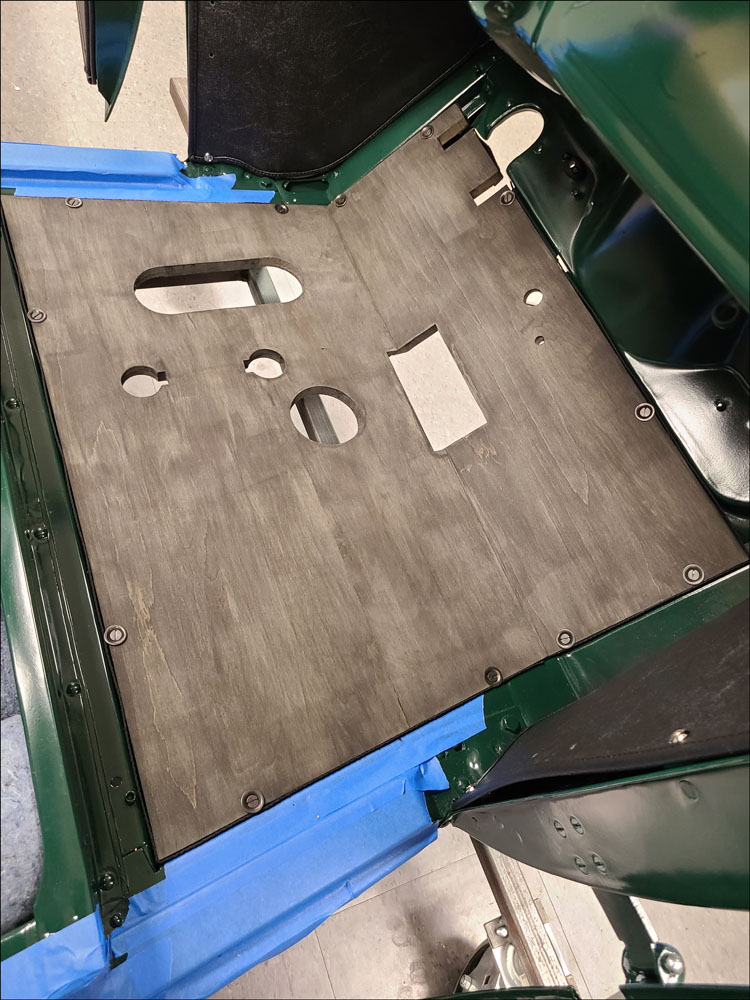
Once the perimeter of the floor board is cut, the boards should be trial fit within the cab floor to determine if any adjustments are needed.
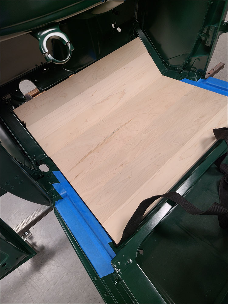
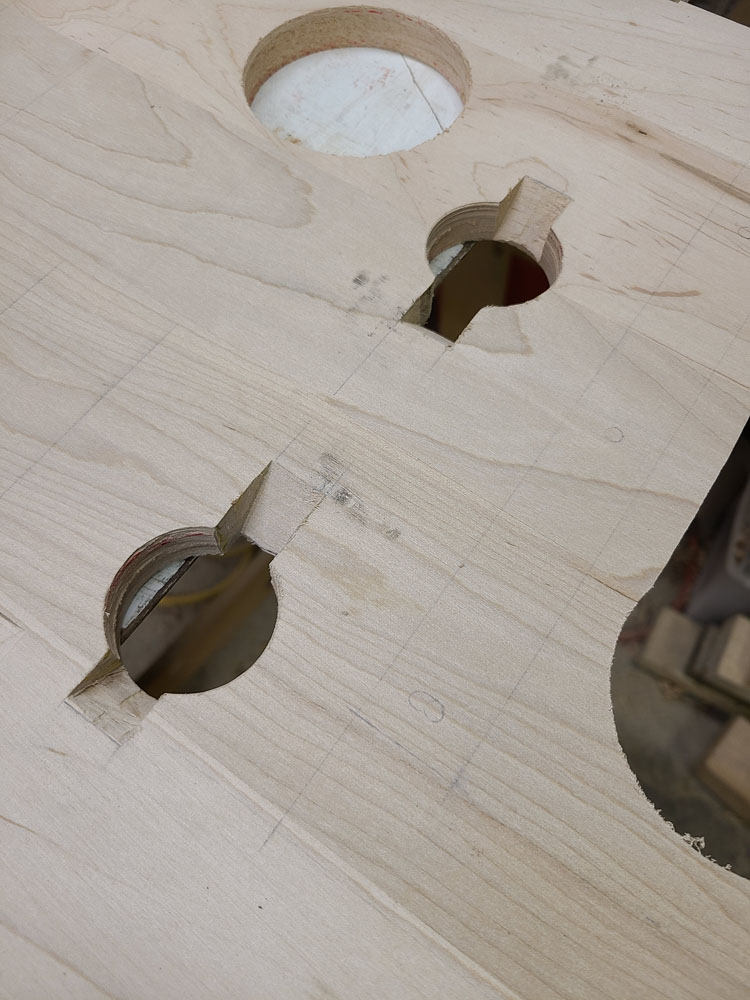
If your cab is on the truck, you will need to cut the clearance holes for any controls that are present, such as accelerator, transmission, and dual-high pedal. If the cab is off the truck as shown in Figure 11, the clearance holes may be cut later, once the perimeter is finalized.
The perimeter fit should be made with floor board welting inserted to ensure that edge clearance is correct. It is not unusual to need trimming of the profile to get a good fit up with the cab, as the cab floor can be out of square or size.
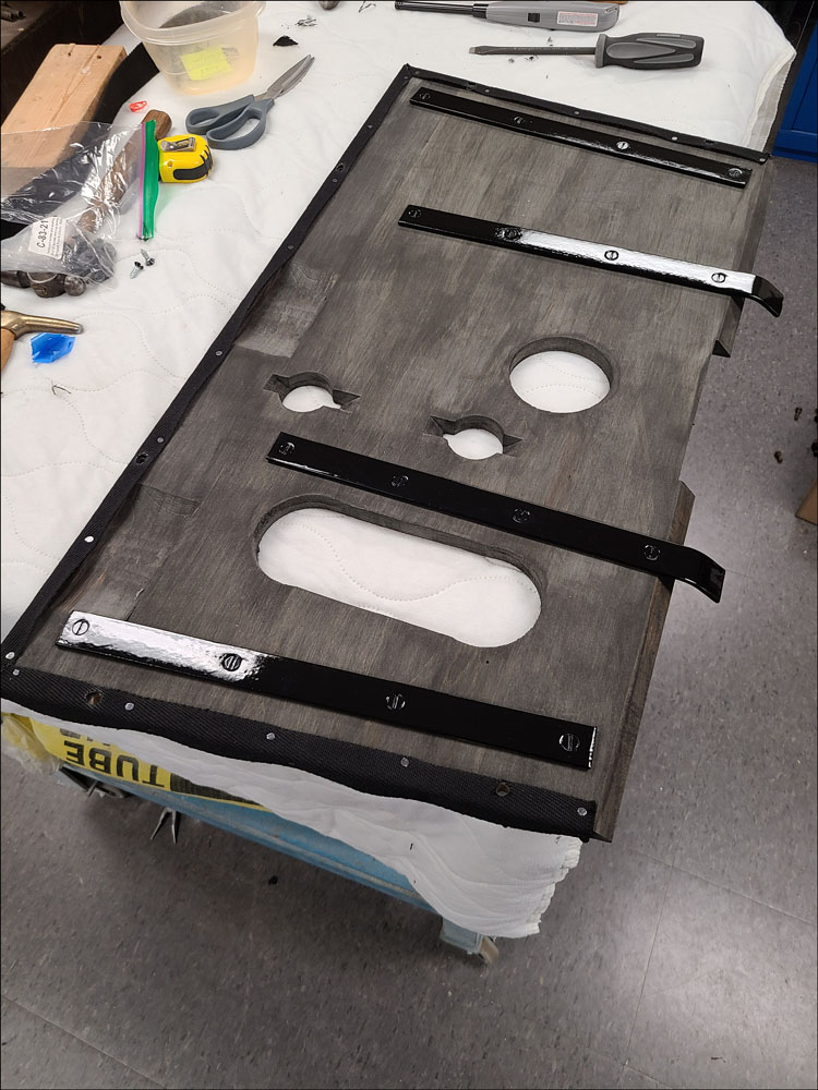
Floor board #2 is reinforced underneath with steel floor board straps (cleats) and beginning in early 1928 they were changed to overlap with floor board #1.
These straps should be trial fit at this time as they will help maintain position between the two floor boards. Straps were either fastened with screws (early) or tubular rivets (later).
After positioning the straps, drill pilot holes for the screws, or through-holes for the rivets. Temporarily fasten the straps with screws and remove once fit up is complete.
Once the perimeter is finished, the floor board mounting screw holes should be located since they will position the floor boards within the floor sills. Again insert the welting but don’t cut it yet, just using it in enough places to locate the boards as shown in Figure 11.
Mark the hole locations by inserting a center punch from the bottom and through the cab rail D-nuts. The front holes on floor board #1 and the rear holes on floor board #2 should be marked first. To properly locate the boards fore/aft, adjust the marks to achieve a 5/16” distance from the edge of the board.
Drill the front and rear holes and re-install with the welting and screws. Ensure a good fit between #1 and #2 floor boards and use the angled reinforcement straps to support both boards.
Mark locations of the remaining screws along the sides of each floor board and drill. This is a good time to final fit the floor boards with all the mounting screws and washers. All the mounting screw holes need to be countersunk from the top to fit the special floor board washers.
Creating Features
Once the floor board mounting holes are complete, the necessary features can be created.
The floor boards in this article were for an early truck equipped with left-side hand brake. It has brake equalizer pin covers, dual-high auxiliary transmission pedal, accelerator pedal, transmission tower, and clutch access cover.
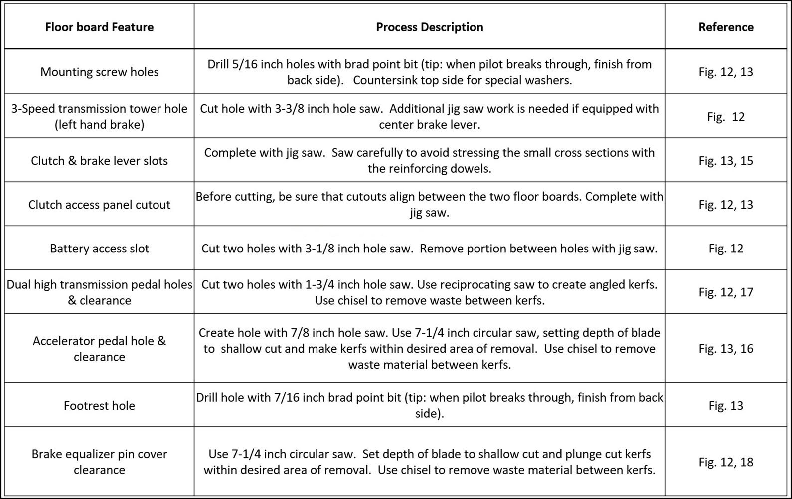
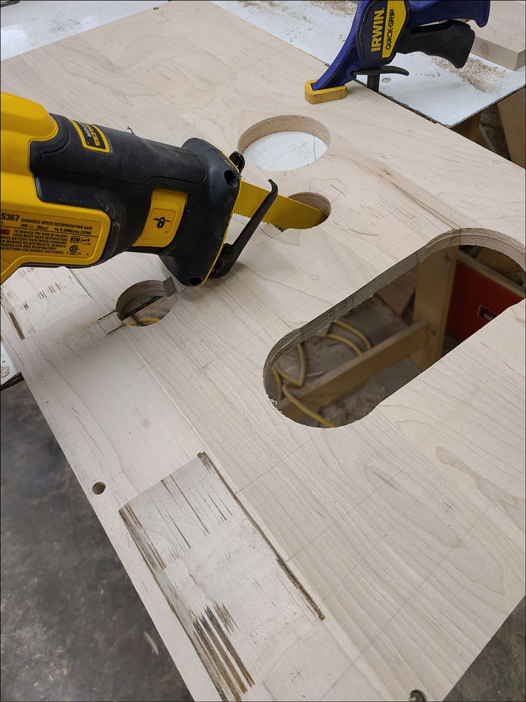
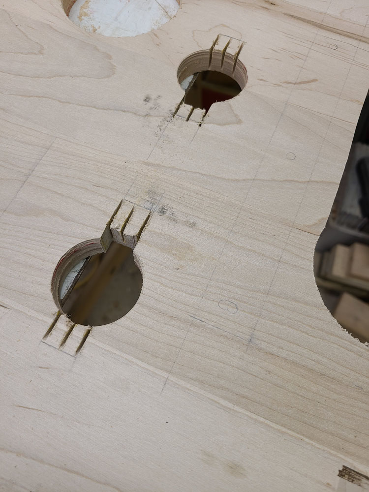
I used a combination of hole saws, drills, jig saw, circular saw and reciprocating saw to create the required features as identified in Figures 12 and Figure 13 (shown from the bottom side).
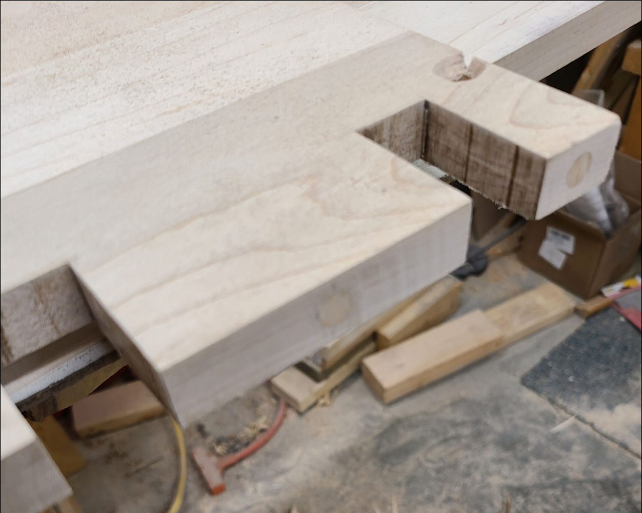
Figure 14 summarizes the processes to create the features, along with references. Review Figures 15—18 for additional details of the features for clutch/brake slots, accelerator pedal, dual high pedal, and brake equalizer cover.
Finish and Welting
Once the floor boards are complete the finish can be applied. Original floor boards were dipped in a dull black wood preservative. I brushed on a couple coats of CreoCoat Black Wood Preservative by Woodlife.
Lastly, the welting can be cut to fit around the perimeter. There is no welting between the two floor boards. The edge of the board is covered with welting, with the top edge of the welting flush with the top surface. The remaining width of welting is wrapped underneath the boards.
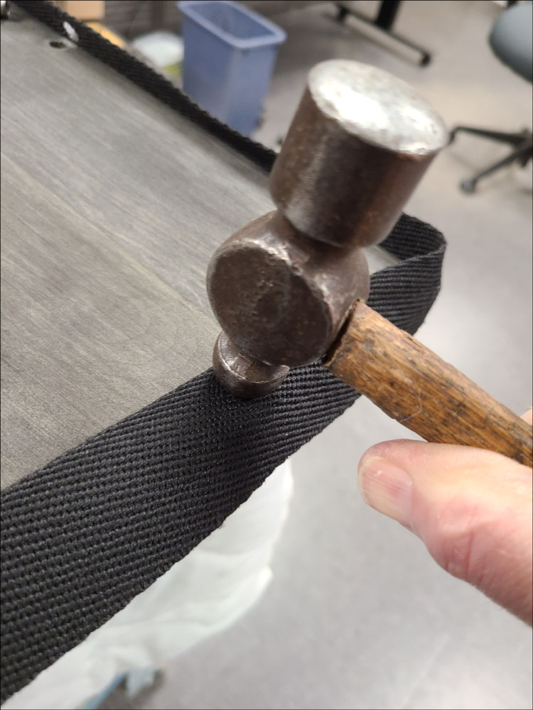
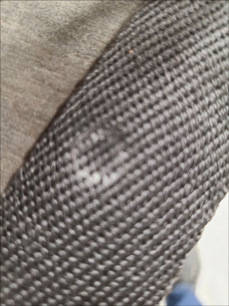
Use the round end of a small ball peen hammer to press an indentation where the mounting screw holes need to be, as shown in Figure 19 and Figure 20.
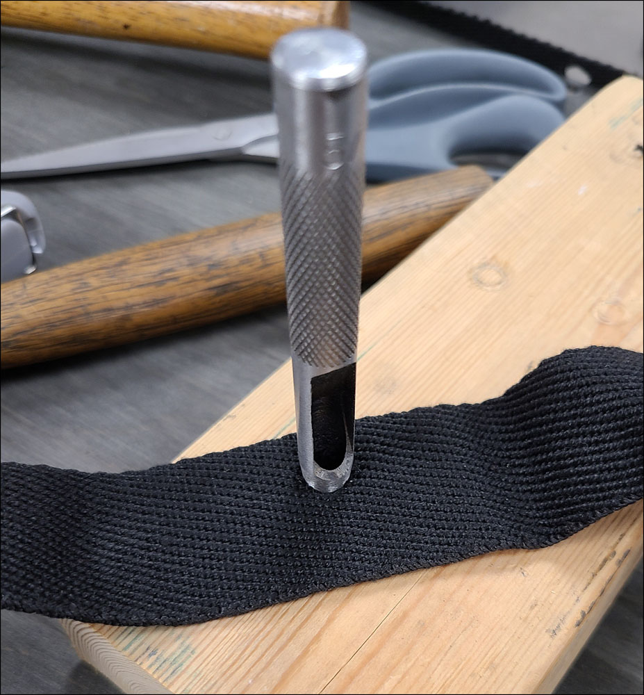
Then use a hole punch to form the hole as shown in Figure 21. The flame from a lighter may be used to lightly singe the holes and ends to prevent fraying.
The welting may then be applied to the sides and wrapped underneath, trimming where necessary and tacking with a minimum number of upholstery tacks to hold in place. Use extra caution when tacking around the clutch and brake slots to not break the small sections with the dowels.
Summary
Figure 22 shows the underneath of completed floor board #2 and Figure 23 shows both completed floor boards assembled into the cab.
List of Tools Used:
- Table Saw
- Planer*
- Joiner*
- Drill Press*
- Router and table with fence*
- 5/16″ x 9° dovetail router bit*
- Handheld Drill
- Brad-point fluted drill bits (5/16”, 3/8”, 7/16”)
- 76° countersink bit (3/4” diameter recommended)
- Hole saws (diameters 7/8”, 1-3/4”, 3-1/8”, 3-3/8”)
- 7-1/4” Circular saw with wood cutting blade
- Reciprocating saw with wood cutting blade
- Jig saw with wood cutting blade
- Chisels (1/4”-1/2”)
- Ball peen hammer
- Tape measure
- Digital calipers
- Square
- Clamps
- Upholstery hammer
- 5/16” hole punch
- Center punch
*required only for hardwood floor boards
List of Materials Used:
- Soft maple boards (11/16” final thickness)
- Waterproof wood glue
- Wood dowels (3/8”)
- Steel reinforcement straps & screws or tubular rivets
- Floor board screws and special washers
- Black wood preservative
- Floor Board welting (approx. 1-1/2” wide)
- Upholstery tacks
References:
- Model “A” Ford Judging Standards & Restoration Guidelines (by MARC & MAFCA) 2016 revision
- AAFords-FMAATC @ https://aafords.com/ (follow: Body Types/Index-Body-Details/Floor Boards)
- The Double A’er Newsletter, https://aafords.com/c/nl/#ta (AA Truck Talk articles on floor boards by Neil Wilson: Issue 13, April 2007 -Floor Boards & Mats; Issue 28, April 2022 -Floor Boards)
- “1909 Ad-Linderman Machine Co. Dovetail Glue Jointer.” Wood Craft, Sept. 1909
To Above – Article “Reproducing Floor Boards” Contents
AA Truck Talk
AA-Chassis Front Bumpers
By Neil Wilson – April 2024
Article Contents
Note overlapping date ranges
********* AA Front Bumpers *********
12/27—5/28 – A-Chassis Service Equip.
5/28—9/28* – A-Chassis Optional Equip.
9/28*—12/29 – A-Chassis Standard Equip.
6/30—10/30 – AA Double-Bar Assembly
11/30—12/32 – AA Single-Bar Assembly
2/31—5/32 – AA Double-Bar Assembly
*9/28 based on RGJS
12/27—9/28 – AA’s Without Front Bumper
No front bumper was provided on the initial AA-chassis. This is confirmed by 1927 Ford photographs as well as the first advertising booklets. One booklet titled “New Ford Car” and another booklet for the AA truck (see pages 4—5 of this “The New Ford Model AA Truck” booklet.
The Indianapolis May 25, 1928 service letter states:
Bumpers On Commercial Cars: We are in position to assemble front bumpers on all commercial cars, such as pickups, and trucks, when requested by the dealer. Therefore, under this ruling, dealers should get in touch with the Car Distributor when he has an order for commercial jobs and knows that he is going to be notified to come after such equipment. When installed, these parts are subject to same discount as the car on which the installation is made, in place of 25% when sold thru service.
Consequently, AA-trucks had no front bumpers except when:
……1 – Dealer service provided equipment – 12/27—5/28
……2 – Ford optional equipment ordered – 5/28—9/28*
……3 – Ford standard equipment – 9/28*—12/29
*9/28 based on RGJS pages E-34 and E-87 (2016 Revision)
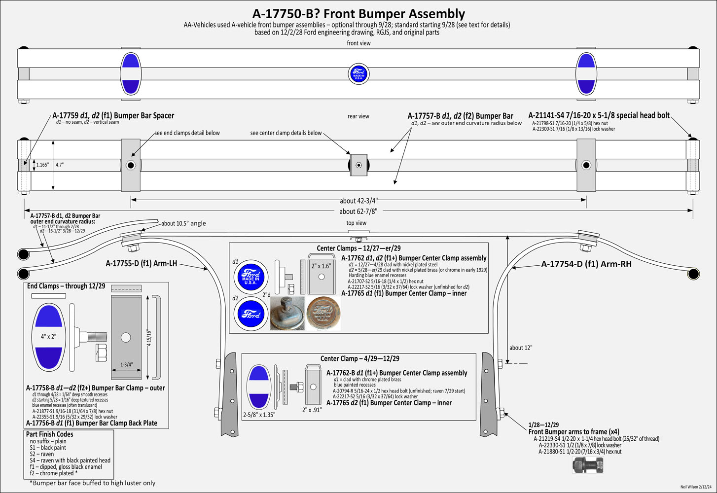
12/27—12/29 – AA’s with A-Chassis Front Bumper
A-chassis front bumper assembly A-17750-B? was used 12/27—12/29. This assembly included the A-chassis bumper bars, end bolts/spacers, end/center clamps, bumper arms and arm-to-frame installation fasteners.
The RGJS Areas 4 and 15 provide details for all of the A-chassis front bumper parts. The RGJS E-4 and E-15 provide usage-date-ranges for A-chassis front bumper assemblies as used on the AA-chassis.
Ford Parts Price Lists show this assembly as A-17750-B. There would have been different assembly designs dependent on the two designs of center clamp and two designs of bumper bar.
Details of this front bumper are shown in the A-Chassis Front Bumper Gallery.
Usage – Front bumper A-17750-B? assembly was provided as listed below. When #1—#2 were not used, then no front bumper was provided.
……1 – Dealer service provided equipment – 12/27—5/28
……2 – Ford optional equipment ordered – 5/28—9/28*
……3 – Ford standard equipment – 9/28*—12/29
*9/28 based on RGJS pages E-34 and E-87 (2016 Revision)
AA’s with A-Chassis Front Bumper Gallery
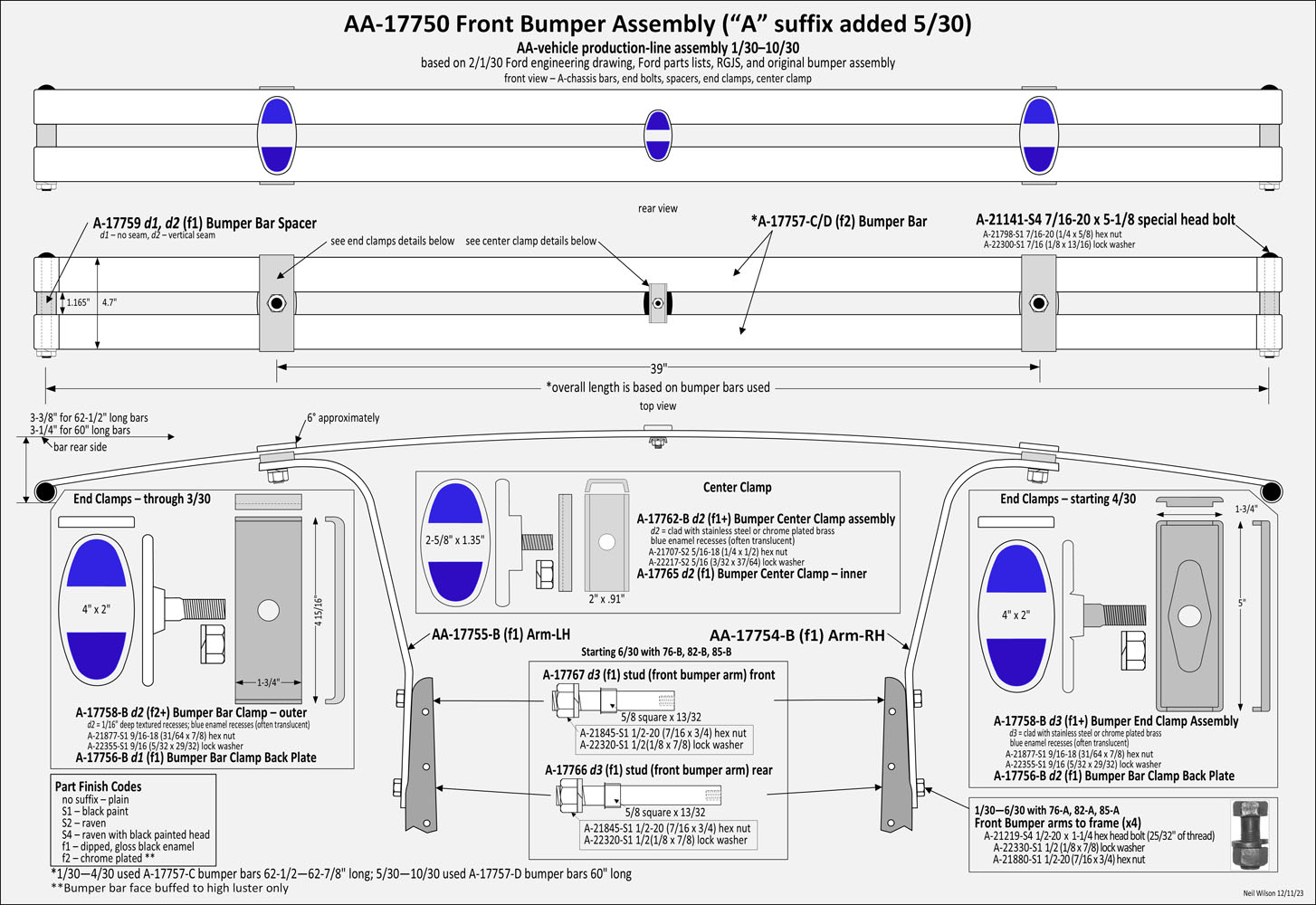
1/30—10/30 AA Front Bumpers with A-Bars + AA-Arms
Front Bumper Assembly AA-17750 was used 1/30—10/30. An “A” suffix was added to the part id 5/30. See the AA-17750 Assembly Gallery for details.
This assembly included both A-chassis and AA-chassis parts:
A-chassis parts of this assembly were the bumper bars (two A-17757-C bars 1/30—4/30; two A-17757-D bars 5/30—10/30), end bolts/spacers, end/center clamps, and arm-to-frame installation fasteners. The bumper bars had an approximately 3-3/8″ or 3-1/4″ outward arch over the length of the bumper when installed (depended on bar length – see gallery drawing).
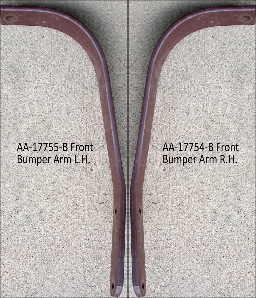
AA-chassis parts of this assembly were bumper arms AA-17754-B RH and AA-17755-B LH.
The AA-arm design placed the bumper end clamp assemblies approximately 39—39-1/2″ apart (center-to-center measurement). This was about 3” closer together than the spacing for the 1928—1929 A-chassis bumper end clamp assemblies.
The outer ends of the bumper arms were angled inward about 6°. This was the contact angle of the arched bumper bars.
Note: The A-chassis 1928—1929 bumper bar assembly will not correctly fit to these AA-arms. The outer bumper clamp spacing would make contact to the mostly flat section of the 1928—1929 bar assembly. Consequently, the bar assembly would be arched outwards with the clamps installed due to the inward 6° angle of the AA-arm outer ends.
AA-17750 Front Bumper Assembly Gallery
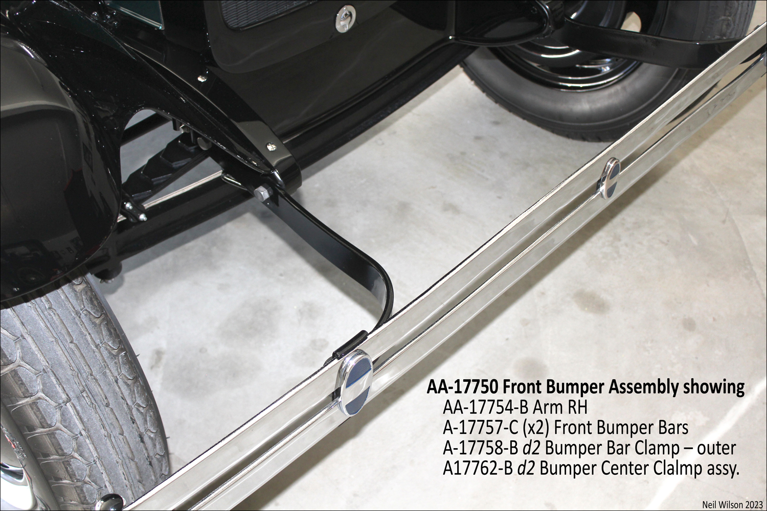
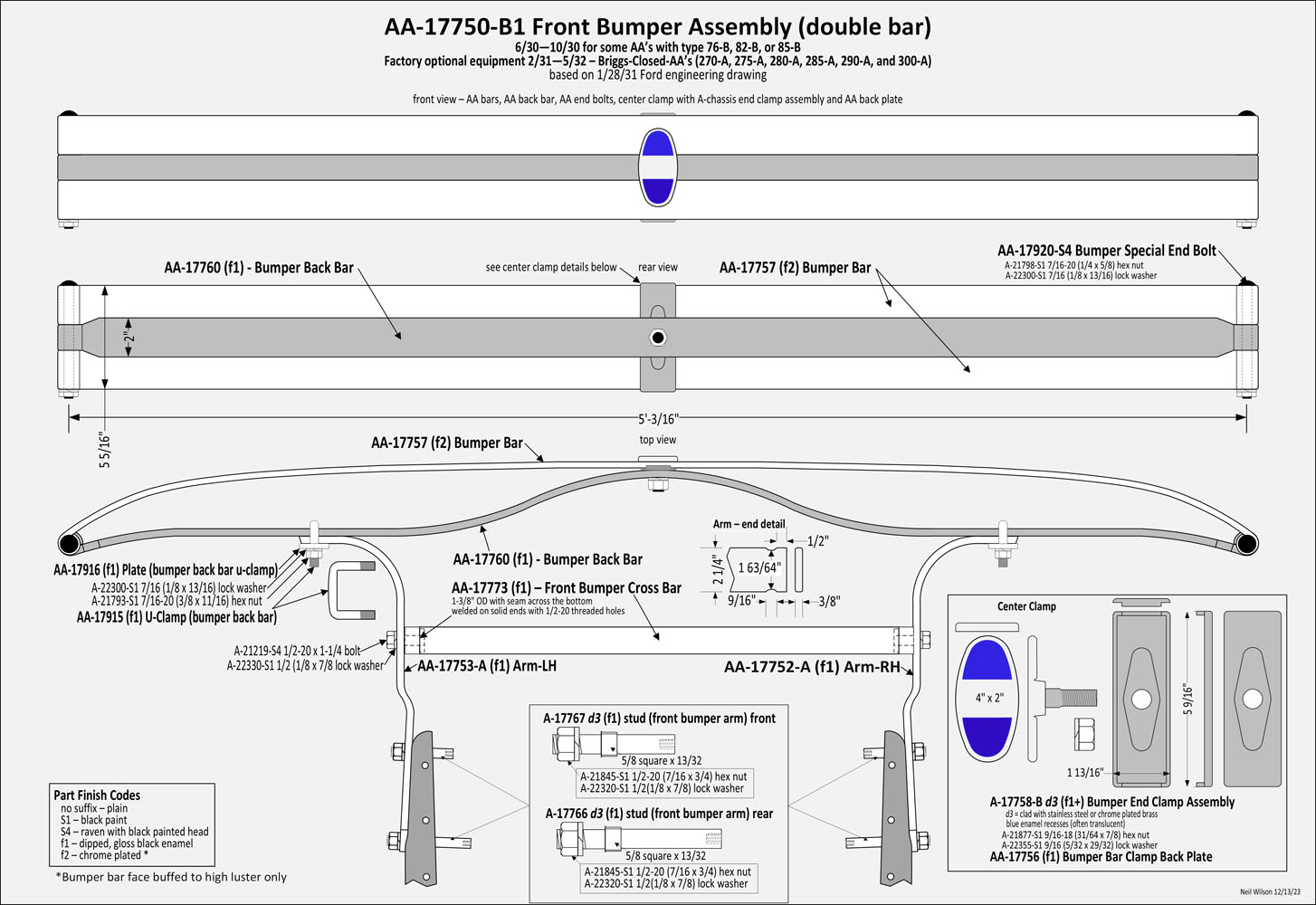
AA Double-Bar Front Bumper Assembly AA-17750-B1
6/30—10/30 – The AA double-bar front bumper assembly was released for use on a few trucks during this date range. This was noted in the Ford Parts Price Lists. It would have been used for AA-vehicles with cab/body types 76-B, 82-B, and 85-B.
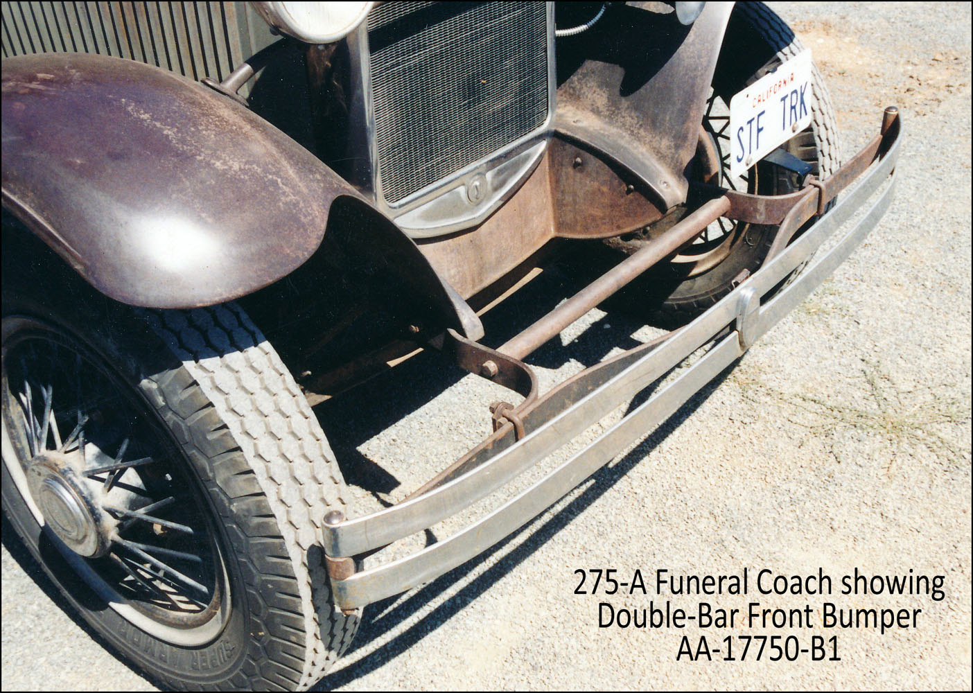
2/31—5/32 – The AA double-bar bumper was again used with the release of Briggs-Closed-AA’s (270-A, 275-A, 280-A, 285-A, 290-A, and 300-A) as optional equipment. These body types may have had either the single-bar or double-bar bumper.
Refer to the AA Double-Bar Gallery for details.
Note – This bumper assembly was initially assigned with id AA-17750-B. It was re-assigned id AA-17750-B1 when the AA-17750-B2 single-bar AA front bumper was engineered in September 1930. The Ford Part Price Lists only shows individual parts for this assembly until the December 1932 Ford Parts Price List. In this list, both the B1 double-bar and B2 single-bar bumper assemblies are listed.
AA-17750-B1 Double-Bar Front Bumper Assembly Gallery
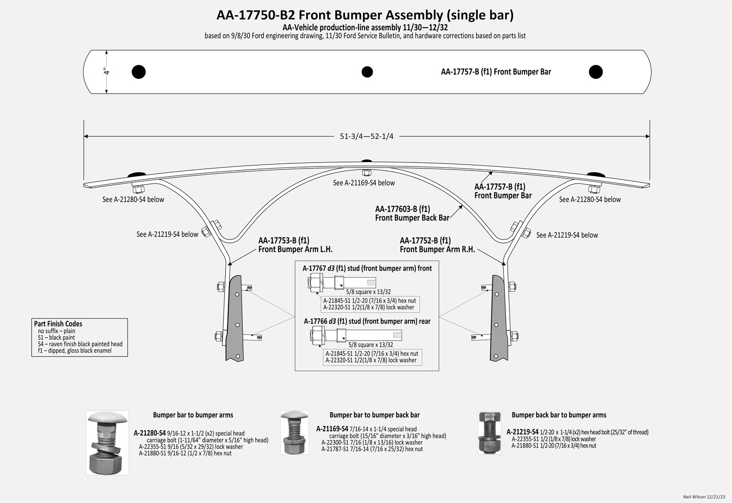
11/30—12/32 – AA Single-Bar Front Bumper Assembly AA-17750-B2
The AA single-bar front bumper was used from 11/30—12/32 (see exceptions). Single-bar details are shown in the drawings in the AA-17750-B2 Gallery.
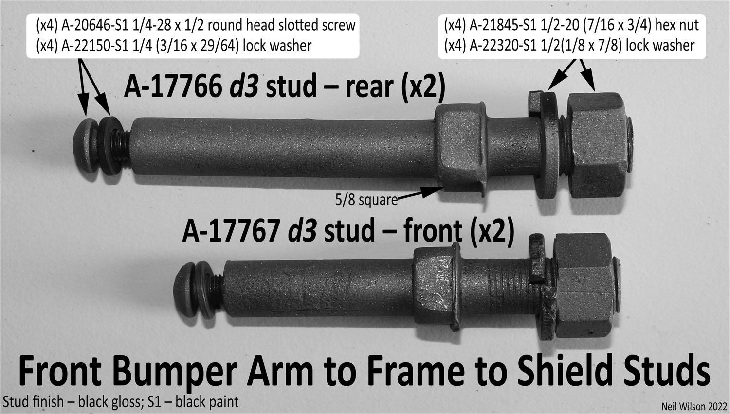
The bumper bar, back bar, and arms were a dipped, gloss black enamel finish. The bolts were raven finish with black painted heads. The lock washers and nuts were finished with black paint.
The bumper bar was attached to the arms with A-21280-S4 9/16-12 x 1-1/2″ special head carriage bolts (1-11/64″ diameter x 5/16″ high heads), lock washers and hex nuts.
The bumper bar to back bar (at the center) was attached with A-21169-S4 7/16-14 x 1-1/4″ special head carriage bolt (15/16″ diameter x 3/16″ high head), lock washer and hex nut.
The arms-to-back-bar were attached with two A-21219-S4 1/2-20 x 1-1/4″ hex head bolts, nuts, lock washers.
The attachment of the bumper arms to the frame used the black paint finished A-chassis design 3 studs.
This bumper replaced the AA-17750-A Front Bumper Assembly and the AA Double-Bar Front Bumper Assembly AA-17750-B1 which was being used on some 1930 AA-vehicles.
AA-17750-B2 Single-Bar Front Bumper Assembly Gallery
To Above – Article “AA-Chassis Front Bumpers” Contents
AA Truck Market
AA truck market classified advertisements are welcome. FMAATC members are entitled to one free ad per issue (as space is available). Ads are to be for Model A/AA vehicles, parts and related items.
Ads must be received by February 15th for the yearly April issue. Ads may include one picture and up to 70 words (each additional word is $0.15). Ads must contain the exact wording with the amount included on for sale items. Submit as an email attachment to fmaatc.org@gmail.com or in type-written form to FMAATC, 1365 Cherryvale Road, Boulder, CO 80303.
Club members with businesses which offer A/AA parts and services may have their business listed under AA Parts & Services Sources. Just send in your information (four lines maximum) to fmaatc.org@gmail.com.
Businesses offering Model A/AA parts and services are welcome to advertise in the Advertisers sections of The Double A’er – Display rates quoted on request to fmaatc.org@gmail.com.
FMAATC accepts No responsibility for the accuracy of any statements, the fairness of any prices, or the quality of any goods and services mentioned in Double A’er advertising.
AA Parts & Services Sources
Joe Davis – Aries Restoration, 16 West Jackson St., Medford, OR 97501; 650-948-6424; jdavis@amuffler.com – restoration services.
Keith Ernst – Tired Truck Restorations – 25 Springhouse Lane; Orwigsburg, Pa. 17961; 570-449-5552; tiredtruck@verizon.net – AA Truck Parts – will send a catalog for an SASE.
Steve Becker – Bert’s Model A Ford Center – 2767 South Tejon Street in Englewood, CO. 80110; 800-321-1931 – A & AA Parts; a catalog is available – parts@modelastore.com.
Tom Godish – Model A Ford Works – 2810 N Ainsworth St; Portland, OR 97217 – 503-282-2212; 10am to 5:30pm
For Sale
NOS wheel studs front and rear, right and left 28—34
Bud Valerius – jbvaa31@outlook.com
785-776-3532; 3605 Windsong Court, Manhattan, KS 66503
(NOS) Nut – spare wheel carrier (30—31 side mount and fender mount style) – 7/8-14 (9/16 x 1-1/4) castle nut – $5.00 each + shipping.
Neil Wilson – 1365 Cherryvale Road, Boulder, Co. 80303 – aafords.com@gmail.com
Wanted
Needing a service truck bed for a 1931 AA service truck! Rodger Johnson 918-629-6177, please leave message.
D article Title??
Article Contents
D article text here??
To Above – Article “title” Contents
FMAATC Meeting
20xx city, st??
text for prior 20xx meeting??
images for prior 20xx meeting??
Advertisers Section

E article Title??
Article Contents
E article text here??
To Above – Article “title” Contents
End – 2024 Double A’er
Exit WebAAer —— to AAer Viewing